
As a part of the humid Southeast, North Carolina’s climate, topography, soils, cropping systems, and water sources require special consideration when considering and implementing a subsurface drip irrigation (SDI) system. This publication is not a step-by-step design manual, but it will help you in the design process of an SDI system appropriate to North Carolina.
Irregularly shaped fields commonly found in humid areas can result in a system layout that differs greatly from the “normal” layout found in the SDI system in an arid or semi-arid area. Installation is best done when the soil moisture is within an optimal range, which may seriously limit the time when a system may be installed in North Carolina. And fewer systems have been installed in humid regions, so fewer professional installers and less installation equipment are available.
This publication presents both design and installation considerations to help the grower in a humid area who is considering a SDI system. Topics include design criteria; pumps; filtration; chemical injection; valves; main and submain (header), dripline, and flushing manifold design; instrumentation and control systems; design implementation; installation tips; and locating an installer.
Introduction
Subsurface drip irrigation (SDI) is similar to surface drip irrigation, but it has driplines that are buried beneath the surface. Some drip systems have lines that are buried up to eight inches deep, but are retrieved annually and are thus very similar to surface drip systems. This publication focuses on SDI systems with lines that are permanently installed below tillage depth (Camp and Lamm, 2003). Although SDI has many important benefits for modern crop production, many challenges also exist. SDI systems must be carefully designed and installed so that they operate with proper efficiency, and so that fertilizers and chemicals can be applied in a legal, uniform, and efficient manner. SDI systems are expensive and should be designed and installed to ensure a cost-efficient system. Significant amounts of technical skill and management are required to properly operate the systems so that peak efficiency and benefits are realized. This means that trained personnel should be involved with the design, installation, and operation of the system. Proper training and management skills are very important to the success of any irrigation operation, and this is especially true with SDI systems in which driplines are buried. While SDI systems have been used successfully for many years in arid and semi-arid locations, the topography, soils, crops, cultural systems, and climate in North Carolina and other humid regions may require a different design and installation.
Before the design of an SDI system is done, determine if the intended site is suitable for SDI. Do you have an adequate water supply, acceptable water quality, and appropriate topography for an SDI system?
Design Criteria
Begin by collecting information needed for a successful design. This information is referred to as design criteria. For an SDI system, these criteria will include information on climate, crops, soils, and water quality, along with system management and operational considerations.
Water Requirements
The SDI system must deliver the required amount of water to the crop at the time it is needed. This is called the “crop water requirement.” You will need to supply the “peak” water requirement, or the amount of water that a crop uses during its highest water use period. During this period of peak water use, your SDI system must deliver that amount of water.
While you may consider rain to reduce the irrigation requirement for a season, do not consider rain when calculating a peak use rate. Even in humid regions, the probability of receiving appreciable rain at a critical period is low. You want a system that can provide water during a drought. In addition, moisture in soil storage is normally not considered when designing for peak demand.
Your peak water requirement is normally lower than in arid regions because we have higher humidity and more clouds, which reduces evapotranspiration. Your crop also influences SDI system design. Different crops and different planting dates will result in different water requirements. If you rotate crops, design your SDI system to meet the needs of the crop with the highest water demand. A good “rule of thumb” is to size your pumps and main lines to replace a peak crop water use rate of 0.25 inches per day. This translates to a pumping flow rate of about 12 gallons per minute (gpm) per acre you plan to irrigate if you run the system 12 hours per day during the peak water use period and factoring in system inefficiencies. You will need to supply a higher flow rate if you will operate it fewer hours per day and less if you can operate it more hours.
Management and Operation Considerations
An essential step in the design of an SDI system is to consider how your use of the area will change over time. It is not enough to design only for next year’s crop. A well-designed system should be in operation for 10 to 15 years, so you must plan for the future. Consider crop rotation, tillage systems, and management capacity in the design process. Row crops and field crops are often rotated. For example, corn and cotton may both be grown in rows that are 30-, 36-, or 38-inches apart without much difference in the production systems. However, winter wheat and soybeans will likely have different traffic patterns than those for row crops, a fact that should be considered when using the SDI system for these other crops.
Water Quality
Water quality will dictate filtration requirements, chemical injection requirements, and management of SDI systems to prevent emitter clogging. Emitters may clog due to chemical (precipitates or scale), physical (grit or particulates like sand and sediment), and biological (such as algae or bacteria) factors.
Groundwater is generally of higher quality than surface water and less likely to clog emitters. Do check iron and manganese levels, as high levels may lead to emitter clogging, and water may need to be treated.
Many existing and potential water supply sources for SDI systems in North Carolina are derived from surface water. The state does not tend to have high levels of salts in surface water, except in some coastal areas. Where salts are not a problem, emitters are safe from salt precipitates than can clog emitters in an arid area. Surface waters, however, tend to introduce biological hazards. If you are considering using wastewater as a source, remember that the quality and clogging potential will vary depending upon the extent of treatment, if any.
Pumps and Power Sources
As with most irrigation applications, SDI uses centrifugal or turbine pumps. Centrifugal pumps are more frequently used to pump water from surface supplies, such as ponds. Turbine pumps (a special type of centrifugal pump) are used to pump water from wells, and they may be either vertical shaft or submersible.
How will you power your pumps? Electricity requires less labor, but it may not be available where you need it. Three-phase power is usually required to operate irrigation pumps greater than 10 horsepower. If electricity is not available or desirable, diesel, gasoline, or propane may be used. The most common alternate power source is usually gasoline-driven engines for small pumps and diesel engines for larger pumps.
Filtration Requirements
Filtration is critical with any drip system. It is even more important in an SDI system as filter failure is costly and determining the location of clogged emitters is very difficult. Design of a filtration system for SDI systems involves selection of filter type and filter size (capacity). The size and type of filter required will depend on the water source and the kinds (if any) of fertilizer and chemical stock solutions to be injected. The pH and the amounts of particulate matter, carbonates, and iron in the water supply will largely determine the filtration system.
The types of filters used most often are sand media (silica sand or crushed granite), disk, and screen. Media filters or disk filters are necessary for any surface water source or wastewater (see Figure 1). In addition, flowing water sources such as a river or stream usually require a sand separator to remove sand before it enters the filter system.
Screen filters are used as secondary filters with surface water systems or as primary filters with well or municipal water sources. Screen filters vary in shape and size. Screen filters may vary in size from 1 inch for 1 acre or less, to 10 inches in diameter. Mesh sizes range from 40 to 200; the mesh size is the number of openings in the filter per square inch. Filters may also be specified by the maximum particle size in microns that will pass – one micron is one-thousandth of a millimeter. A 200 mesh size is equivalent to 74 microns and a 120 mesh size is equal to 125 microns. Fine sand has a diameter of between 125 and 250 microns, so a 120 or greater mesh will filter fine sands and larger particles.
Disk filters can be used as primary or secondary filters with surface water systems and be used as primary filters with well or municipal water sources. These filters contain a series of grooved plastic disks. Equivalent screen size ranges from 40 to 400 mesh (Hanson, et al., 1997) with 40 to 200 mesh being the most common. Disk filters have more surface area than screen filters and are, therefore, better suited for higher flow rates. They are also easier to clean. For any filtration system, the level of filtration (effective mesh size) is dictated by the emitter and passageway size. In general, the smallest filter opening should be one-tenth the size of the smallest emitter passageway.
When designing a filtration system, consider filter flushing. Most filtration systems are designed for either manual or semi-automatic, or automatic flushing. Flush cycles for manual and semi-automatic flush systems are manually activated. Flush cycles for automatic systems are activated either when a pre-set pressure differential across the filters is exceeded, or by a pre-set operational time interval. Selection of filtration automation depends upon cost and labor considerations.
Both media and disk filters require a minimum pressure downstream of the filters during the back flush cycle. For media filters, the required pressure is normally 30 pounds per square inch (psi) and for disk filters it is typically 40 psi. It may be necessary to install a pressure sustaining valve downstream of the filters that actuates during the flush cycle to maintain the back pressure necessary to flush properly.
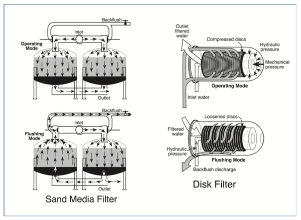
Figure 1. Media and disk filters used in SDI systems.
Courtesy of F.R. Lamm, Kansas State University
Chemical Injection
Chemigation is an inclusive term that refers to both injection of chemicals to prevent or ameliorate emitter clogging (chlorine or acid), and the injection of chemicals for your crops (fertilizers and pesticides). Because drip emitters are small, they clog easily. Along with filtering water, the capability to inject chlorine and acid is important in preventing clogged emitters. High humidity conditions common in North Carolina accelerates algae production, so chlorination is very important if algae are present in the water supply. Other benefits of chemigation are uniform and timely application of fertilizer, reduced soil compaction due to reduced traffic in fields, reduced labor requirements, reduced exposure to chemicals, and reduced risk of environmental contamination.
The design of a chemical injection system involves the selection of injector type and capacity. If the injection system is to be used to apply fertilizer through your irrigation system (fertigation), size the injection unit for this use since injection rates for fertilizers are usually much higher than injection rates for chemicals like liquid chlorine or acid that are added to prevent emitter clogging. Two basic types of injection systems, the Venturi injector and the metering pump, are commonly used for injecting fertilizer and other chemicals into drip irrigation systems. Metering pumps may be positive displacement piston-type pumps, or diaphragm-type pumps. If a diaphragm injection pump is selected, be sure that the rated pressure is at least as much as the pressure you will have at the pump, otherwise the injection pump will not deliver its rated flow. Be sure that the injection system has an adjustable injection rate. Any components that will be in contact with fertilizer, chlorine, or acid should be resistant to corrosion. Any chemical injection system should be placed so that chemicals are injected upstream of the filtration system.
Always follow state laws and chemical labeling requirements. Wade, et al. (2003) provides North Carolina guidelines for the legal and safe injection of chemicals.
Valves
As with any drip irrigation system, proper selection and placement of valves are critical. Water flow rate and pressure throughout the SDI system should be precisely controlled to ensure efficient and timely water application. Valves play key roles in controlling pressure, flow, and distribution under different conditions to optimize performance, facilitate management, and reduce maintenance.
Valves used in a complete SDI system include check valves, shut-off valves, pressure relief valves, remote-control valves, pressure regulators, and air and/or vacuum relief valves. Valve sizes, maximum working pressure, and valve materials should be selected properly to meet your system’s demands. Oversized valves may not open or close properly and undersized valves may restrict flow and cause excessive pressure loss. Undulating topography means that extra care will be needed in properly locating air and/or vacuum relief valves at high points in the system.
Main and Submain Design
Proper design guidelines for mainline and submain piping generally follow normally accepted design practices for surface drip and/or sprinkler irrigation systems. Submains, as defined here, are the same as supply manifolds for the dripline. Supply manifolds are sometimes called “headers.” See Figure 2 for a typical SDI zone and components. In normal irrigation design, pipe size is based on economic, friction loss, and water hammer considerations. In an SDI system, you must also consider sizing pipe to flush the system. As pipe size increases, friction loss decreases (reduced pumping cost) but initial cost increases. Main and submains are normally “telescoped” or reduced in size as water is discharged, reducing pipe cost. The major difference between the design of “normal” irrigation systems and SDI systems is the increased importance of proper flushing, including the flushing of mainlines, submains, and driplines. The piping system must be designed not only to allow the flow rate necessary for normal irrigation but also to allow flow rates to ensure proper flushing velocities in the system. Keep submains and flushing manifolds below the driplines so that solids will tend to collect in the submains and flushing manifolds rather than in the driplines.
In humid regions, irregular field shapes are common due to topography and property boundaries. Carefully size submains where field shape varies. Each dripline lateral may have a different length and a different total flow rate. Base design for submains on actual flow rates of the driplines and not on an “average” flow rate. Pipes for flushing may also have differing pipe diameters because the flushing flow rate required to achieve a desired flushing velocity in any section of a main or submain may be different than the design flowrate (normal operation).
There are two basic flushing design procedures:
-
Size mainlines and submains for normal operation (irrigation only).
-
Size pipe based upon a required flushing flow and velocity.
When designing for irrigation only, achieve the required flushing flow and velocities in the mainlines by adjusting the number of zones flushed at one time. When designing for flushing, place valves at the distal end and size in conjunction with the pipe to allow flushing flows and velocities in the larger diameter sections. In an above-ground drip system, you may flush submains by adjusting the number and location of driplines flushed in the zone. In an SDI system, you cannot alter the number of driplines flushed within a zone. When designing a submain for irrigation only, the last section or two of pipe, where operating flows are low, may have insufficient flushing velocities. Size the piping system to allow flushing of the entire main or submain to allow a more thorough cleaning if the need should arise. When designing the system specifically for flushing, the design should aim for velocities of at least 1.0 foot per second in the largest section of the main or submain when in flushing mode.
Sometimes an irrigation zone is split into two sections and manual valves on either half of the submain allow flushing of half of the zone at one time (see Figure 2, lower drawing). This gives you flexibility and allows for adjustments in flushing flow velocities. While telescoping the submain is done to ensure adequate flushing velocities in the submain, too much telescoping may ultimately result in excessive friction loss in the flush mode. This may result in inadequate pressure at the dripline inlet to maintain adequate flushing flows and velocities in the dripline.
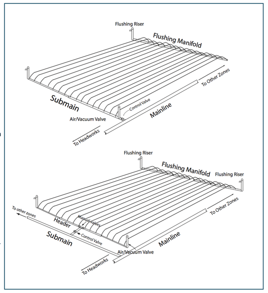
Figure 2. Typical SDI zone layouts. Lower layout separates zone into two sections for increased flushing capabilities.
Dripline Design
With any irrigation system, the design process starts at the plant and works upstream. Hydraulically speaking, this means dripline design (dripline selection, specification of dripline depth and spacing) comes first. Dripline selection involves consideration of emitter spacing, dripline diameter and wall thickness, and emitter flow rates. Also consider connections between the dripline and the supply and flushing manifolds.
Dripline selection will depend upon plant spacing, soil characteristics, and dripline durability and hydraulic characteristics. Dripline diameters range from 3⁄8 inch to 13⁄8 inch, and flow rates range from 0.17 to 1.00 gpm per 100 feet of dripline. While rigid tubing can be used in SDI systems, drip tape is normally chosen due to its relatively low cost. A minimum drip tape wall thickness of 15 mil is normally specified. Rigid tubing, rather than drip tape, is sometimes used on sandy soils that do not bridge.
Another consideration is clogging potential. In general, higher flow rate emitters tend to clog less due to larger flow passages (Hanson et al., 1997). Also consider your soil. Lower emitter discharge rates may be required on heavy textured soils, such as clay, so that the discharge rate does not exceed the hydraulic conductivity of the soil. If the discharge rate is too high, “surfacing” may occur as water takes the path of least resistance to the surface via void spaces.
Dripline depth must be specified. Most systems installed to date in agronomic, turf, and forest crops have placed the dripline between 4 and 18 in below the soil surface (Camp, 1998). In general, dripline depths should be shallower in coarser textured soils and deeper in finer textured soils. Although soils in North Carolina often lead to a restriction in the depth of the root zone, driplines will need to be installed deep enough to avoid damage from tillage equipment. If deep tillage is required (at or deeper than the dripline), tillage must avoid the driplines so precise knowledge of dripline location is required. While historically this has been a problem, precision guidance systems may reduce the risk of accidental dripline damage.
Dripline spacing, like depth, depends on soil characteristics as well as the crops to be grown. In general, coarser textured soils will require a narrower dripline spacing than a finer textured soil, since there is less lateral water movement in coarse soils. Oftentimes a critical crop in your rotation will dictate spacing. In rotations that include a row crop, dripline spacing is most often a multiple of row spacing. Alternate middle rows are common when driplines are spaced on a two-row spacing.
Dripline length is determined by field length and layout, allowable pressure (and therefore flow) variation within a zone, and flushing considerations. Irregularly shaped fields may have driplines of different lengths. Flow variation in an SDI system is normally expressed by emission uniformity (EU), which is defined as the ratio of the average of the lowest quarter of emitter flow rates to the average emitter flow rate. The general rule of thumb is to design for a dripline lateral EU of 90 percent. Most manufactures publish allowable dripline lateral lengths to maintain a desired uniformity along the dripline. Driplines need to be periodically flushed, and the length of dripline laterals will impact required flushing times. Longer lines need longer flushing times, both to flush any soil particles or organic material out of the line, and to purge any chemicals that may have been introduced into the system.
Dripline Flushing Manifold Design
The flushing manifold at the end of the driplines is fitted with a flushing riser (see Figure 2) and valve to allow flushing of the driplines. When the flushing valve is opened, flow rates and velocities through the driplines are greater than those in normal operational mode. The higher flow velocities remove settled solids and precipitants from the system to help prevent emitter clogging.
Flow regimes may be quite complicated in irregularly-shaped fields with different lateral lengths within the same irrigation zone. Since SDI zones are closed-loop systems, however, pressure tends to equilibrate and zones with differing lateral lengths can be designed using an average lateral length.
Determine flushing manifold pipe sizes by considering the flow through the end of the driplines during flushing. Size the flushing manifold for a flow velocity of at least 1 to 2 feet per second through the laterals to ensure sediment removal from the laterals (Lamm et al., 2007). Flushing manifold pipe diameter inceases in the direction of the flushing riser. It is recommended that telescoping of the flushing manifold be limited to three equal-length sections and that the smallest pipe diameter be limited to about two-thirds of the largest pipe diameter (Lamm and Camp, 2003). Flushing will increase the flow requirements of the system temporarily, which in turn will decrease the system pressure. In some cases, you may not be able to reach the desired velocity, especially with pressure-regulated zones. Similarly, some irregular field shapes may require large amounts of piping to connect the ends of all the driplines in a particular section or zone. When zones are relatively large, the pumping system may not be able to supply the flushing flow rates required to achieve the desired velocity at the ends of the driplines. In that case, separate the irrigation zone into two or possibly three separate flushing manifolds. This separation will allow a proper flushing pressure to be maintained.
A careful balance between flushing velocities in the manifolds and in the driplines is critical when designing SDI zones. Several drip tape manufacturers have software that calculate dripline inlet flushing pressures required to achieve a 1-foot–per-second flushing velocity with an assumed level of back-pressure at the end of the dripline. Other guidance on flushing manifold design may be found in Lamm and Camp (2007).
Instrumentation and Controls
Fortunately, components for automating irrigation systems are common. Automation can pay for itself by reducing labor requirements and by enabling more precise irrigation. A relatively permanent SDI system lends itself to automation. Basic instrumentation starts with meters that help monitor system performance and that help diagnose potential problems. Make sure the installer provides flow meters at strategic locations, such as submains, for system monitoring and to potentially provide feedback for irrigation control. Pressure gages are also vital in an SDI system to monitor pressure and help diagnose problems. Low pressure and/or increased flow rates during normal operation can help you locate a leak.
Irrigation control systems may be “open” or “closed” loop. Open loop systems do not incorporate feedback; you set the amounts and timing of irrigation. Usually a simple irrigation controller operated with a clock is available commercially. In general, these controllers initiate irrigations at preset times and control the duration of irrigation by activating solenoid control valves that serve the irrigation zones. The controllers vary in the number of valves that can be controlled, the number of valves that can be simultaneously held open, the number of separate irrigation programs available, and the number of start times available for each program. These controllers are not normally set to operate with feedback, although most offer a rain switch that terminates irrigation during precipitation.
Since humid areas like North Carolina by definition have appreciable rainfall, soil moisture may change unpredictably, making it difficult to schedule irrigations. As such, a closed looped system using feedback from soil-moisture sensors to interrupt or adjust irrigations offers many advantages. Automation of irrigation using feedback can prevent leaching of chemicals and reduce pumping costs by irrigating only when the crop needs it. Damage from lightning is the biggest concern for fully automated irrigation systems in humid regions.
Implementing the Design
It is important that the installer of an SDI system, whether they are an irrigation dealer, a contract installer, or a grower, realize the importance of installing the system exactly as designed. Site, crop, and management specific issues (e.g., dripline spacing, depth, and length, emitter spacing, zoning, and control and air valve locations and specifications) should have been considered in the design of the system and so should be installed accordingly. Use caution when considering a change in the dripline or other specified components because of cost or other considerations. Changing a dripline should only be considered if the flow rate, pressure rating, and wall thickness are equivalent to designer specifications. If not, the system hydraulics will be changed and dripline life may be shortened.
It may be possible to change the design slightly as long as performance is not compromised. For example, the connections from the driplines to the manifold may change if specified parts or connectors are not available from a local dealer, or if it makes installation easier. If changing parts make sure they are hydraulically equivalent and be aware that any changes made to the system can affect its performance. Consult the designer before any changes are made. Critical components, such as air and vacuum valves, must always meet design specifications. Any changes to the system should be noted on an “as-built” drawing. These are copies of the original design that show any modi cations that were made during installation.
Begin installation by laying out the system on the field. Stake where the driplines and manifolds are to be buried, or “bed up” furrows or use a planter to delineate rows. In either case, it is important to set enough reference stakes so that the system will be installed as designed. Always install permanent markers so that manifolds and lines can be located after installation for maintenance and planting purposes.
Dripline burial depth and consistency of placement are very important. If lines are too deep, there won’t be enough water near the surface for germination, but if it’s too shallow, tillage practices may be restricted (Lamm et al., 1997). The “proper” depth of dripline and manifolds varies depending upon the crops that will be grown and planned cultivation practices. Recent advances in installation equipment and guidelines have resulted in more consistent installation of SDI systems (Camp et al., 2000). Examples of tape injection machines are shown in Figure 3. Gage wheels or skids used during installation to help place the drip tube at the design depth will reduce placement depth variability. If you “bed up” the field before installation, it is important to know the reference (top of bed, furrow, or midpoint) from which dripline depth will be measured.
Timing of installation can be important, especially if you have clay soils. Soil moisture is a critical consideration when installing lines in clay soils and will affect draft requirements and soil disturbance due to the installation shank. In some cases chiseling or subsoiling of the field may be done before installing the driplines. This eases installation and breaks up any compacted layer that might promote surfacing of water applied by the dripline. On the other hand, the soil fracturing may delay “settling” of soil around the dripline, potentially limiting water movement initially. Close chisel shank marks at the surface to prevent rodents from damaging the dripline. Use a drag bar behind the injector shank or lightly disk or use a rolling cultivator. In heavy soils, the soil should be dry enough that smearing of the side walls of the dripline channel does not occur. Fall may be the best time to install an SDI system in North Carolina, since the soil is normally drier, and it allows time for soil to settle before planting.
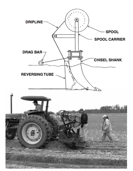
Figure 3. Custom-made dripline installation tool is shown in the top diagram (courtesy of F.R. Lamm, Kansas State Uni- versity); installing dripline with commercial installation tool is shown in lower photograph.
Installation Tips
If you are installing the system, take the time to talk with knowledgeable consultants, distributors, designers, and other users of SDI systems. This will help you avoid installation problems. Substantial knowledge is available, but it is not readily available in written form. Each component of the SDI system has been designed by the manufacturer, and selected by the designer to provide maximum life and benefit. However, improper installation can destroy much of its effectiveness. The following list of tips may be helpful to make installation easier and successful:
-
Make sure pumps have adequate capacity to provide for both irrigation AND flushing. To have adequate flushing capacity, you may need to install additional zone control valves.
-
Make certain all above ground equipment (especially air release valves, zone control valves, and flushing risers) are located out of the way of field equipment and traffic (roads) or they are well protected and well marked for visibility.
-
Check installation equipment frequently for damage. Rocks or other items can create a “burr” on the installation equipment that can damage the drip tape, causing substantial leaks in the system after installation.
-
Install driplines so that the emitter openings face upward. This will help keep materials that have settled out in the tape from entering and clogging the emitter.
-
Verify the dripline location each year before planting. The newly planted crop must be properly spaced from the tape. If you aren’t using precision GPS technology, place a metal ring or other small metal object around the tape at the beginning and ending of the first (or multiple) row. You will be able to locate it with a relatively inexpensive metal detector.
-
To help with maintaining dripline depth placement, turn off the “load control” or “draft” setting on the tractor used to pull the installation plow. This will allow the use of the gage wheels on the plow to maintain tape depth despite varying soil conditions.
-
Most dripline connector leaks can be avoided by simply making sure that the dripline is cut “square” and “clean.” Dripline cuts that have been “stretched, pulled, or uneven” will not make a good leak-free connection.
-
Protect all control wire and water piping, especially where it enters or comes out of the ground. Future damage from rodents, chemicals, or weed trimmers will be difficult to locate. It is best to take steps to prevent wire damage from happening. Enclose any aboveground control wire in a conduit.
Locating an Installer
Subsurface drip irrigation systems are not common in North Carolina, so there are not many people with experience in system installation. Irrigation dealers may provide installation services in addition to system design and sales. Growers who have had SDI systems installed in the area may also be a source of information. Dealer representatives of dripline products oftentimes know an installer, or may even provide installation equipment especially if their product is being used. Manufacturers of dripline installation equipment may also have information on local installers.
Any installer should provide references. Be sure to check them. Bonding or certification from the Irrigation Association may be an indicator of a reputable installer. Additional sources of information about installers and other SDI topics may be found on the internet.
Summary
The proper design and installation of any irrigation system, and especially an SDI system, are critical. In North Carolina, design and installation considerations differ from those in arid regions. Use the information on design considerations to guide you in the design process of an SDI system that will work in your fields. Then work with an industry representative and dealer or consult with your local N.C. Cooperative Extension agent to find someone to help you with your design.
References
Camp, C.R. and F.R. Lamm. 2003. Irrigation systems, subsurface Drip. Encyclopedia Water Science. Marcel Dekker, New York, NY. pp. 560-564.
Camp, C.R., F.R. Lamm, R.G. Evans, and C.J. Phene. 2000. Subsurface drip irrigation—Past, present, and future. Proceedings of the 4th Decennial National Irrigation Symposium, Nov. 14-16, Phoenix, AZ. pp 363-372.
Camp, C. R. Subsurface drip irrigation: A review. 1998. Trans. ASAE. 41(5):1353-1367.
Hanson, B., L. Schwankl, S. Grattan, and T. C. Prichard. 1997. Drip irrigation for row crops. Publication 3376, University of California Irrigation Program, University of California, Davis.
Lamm, F. R., D. H. Rogers, M. Alan, and G. A. Clark. 2003. Design considerations for subsurface drip irrigation systems, Kansas State University Agricultural Experiment Station and Cooperative Extension Service Bulletin MF-2578.
Lamm, F. R. and C.R. Camp. 2007. Chapter 6. Subsurface drip irrigation. in Microirrigation for crop production, pp. 473-551. Elsevier Freddie R. Lamm, James E. Ayars, and Francis S. Nakayama (Editors)
Lamm, F. R., G. A. Clark, M. Yitayew, R. A. Schoneman, R. M. Mead, and A. D. Schneider. 1997. Installation issues for SDI systems. Presented at the 1997 ASAE International Meeting, Minneapolis, MN. August 10-14, Paper No. 972074.
Wade, H., D. Seal, C. Clark, B. Walls, K. Messick and G. Grabow. 2003. Chemigation and fertigation: Anti-pollution devices for irrigation systems. Prepared by North Carolina Department of Agriculture & Consumer Services and North Carolina State University.
This factsheet is part of a series dealing with SDI in North Carolina. The following titles also are available:
Acknowledgments
Contributions to this factsheet were made by faculty of Cooperative Extension, the Agricultural Experiment Stations and universities in Arkansas, Florida, Georgia, Kansas, Louisiana, Maryland, North Carolina, South Carolina and Tennessee, and the USDA-ARS in Georgia and South Carolina. Activities that resulted in the publication of this document and the companion documents listed were supported by the CSREES multi-state S-1018, "Irrigation Management for Humid and Sub-Humid Areas" and the ASCE/EWRI Irrigation and Drainage Council-On-Farm Irrigation Committee-Task Committee on "Subsurface Drip Irrigation Application for Humid Regions."
Publication date: April 1, 2008
AG-695-03
N.C. Cooperative Extension prohibits discrimination and harassment regardless of age, color, disability, family and marital status, gender identity, national origin, political beliefs, race, religion, sex (including pregnancy), sexual orientation and veteran status.