
Introduction
A recent assessment of the rivers and streams in the United States revealed that 45 percent are unfit for recreational, drinking water, or other uses, with sediment and siltation as the leading causes. Construction activity can contribute significantly to sediment loading, with erosion rates up to 100 times that of cropland. Concentrations of suspended sediment in construction site discharges have been measured at over one pound per gallon.
On most construction sites, channels are installed to route runoff into sediment control basins. To keep the channels from eroding, check dams are usually installed to reduce the flow rates and pool the water so it moves down the slope gradually (Figure 1 and Figure 2). The most common practice is to place large stone in the channel with a weir, or low spot, in the center. An alternative approach is to use wattles or logs made of natural fibers such as straw, coir, wood fiber (excelsior), or compost. Such fiber check dams (FCDs) have recently proved to be both more effective and more economical than rock check dams in construction site channels. Most FCDs are relatively light and can be easily installed by one person in about 15 minutes. Unlike rock dams, FCDs do not have to be removed after construction is complete. When installed adjacent to roads, they are also much less likely to damage vehicles that accidentally enter the ditch. This factsheet provides the basic guidelines for installing FCDs.
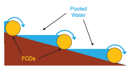
Figure 1. A cross-section of a ditch shows that FCD spacing should create a series of pools to prevent scouring and to encourage sedimentation and vegetation establishment.
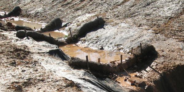
Figure 2. An example of an installed FCD system pooling water in a ditch line.
FCD Installation Procedure
The first step is to determine the proper spacing. As mentioned previously, check dams should pool water to prevent channel scouring. The distance between the FCDs is based on the slope of the ditch, with steeper slopes requiring closer spacing. The elevation of the top of the center weir should be the same elevation as the base of the FCD upslope, creating a series of pools during storm events. This step-pool sequence prevents runoff from gaining excessive velocity as it flows downslope, reducing scouring and aiding in sediment removal. The pooling effect may also help establish vegetation, as germinating seeds are not swept away. Table 1 shows the spacing required for pooling by three common FCD diameters.
| Ditch Slope (percent) | 9" FCD Diameter (ft.) | 12" FCD Diameter (ft.) | 18" FCD Diameter (ft.) |
|---|---|---|---|
| 1 | 75 | 100 | 150 |
| 2 | 38 | 50 | 75 |
| 3 | 25 | 33 | 50 |
| 4 | 19 | 25 | 38 |
| 5 | 15 | 20 | 30 |
| 6 | 13 | 17 | 25 |
| 7 | 11 | 14 | 21 |
| 8 | 9 | 13 | 19 |
| 9 | 8 | 11 | 17 |
| 10 | 8 | 10 | 15 |
| 11 | 7 | 9 | 14 |
| 12 | 6 | 8 | 13 |
| 13 | 6 | 8 | 12 |
| 14 | 5 | 7 | 11 |
| 15 | 5 | 7 | 10 |
| 16 | 5 | 6 | 9 |
| 17 | 4 | 6 | 9 |
| 18 | 4 | 6 | 8 |
| 19 | 4 | 5 | 8 |
| 20 | 4 | 5 | 8 |
Before FCD installation, a section of geotextile or other erosion control blanket must be installed underneath the FCD. For lined channels, this is not necessary. The fabric is needed to prevent scouring, which can occur as the water passes over the FCD. Some FCDs come with attached ”flaps” or ”wings” of material that are stapled into the soil to anchor it and to provide a splash pad on the lower side (see Figure 5). The FCD must be installed perpendicular to flow with a weir, or low point, that can pass the design flow without overtopping the channel or passing around the FCD ends (Figure 3). It is crucial that the full length of the FCD is in solid contact with the ground, which may require tamping the FCD forcefully so it adequately conforms to the ditch profile. Plug any remaining spaces with cut sections of erosion control blanket or similar material. Gaps will scour and undercut the FCD, rendering it ineffective and possibly causing excessive erosion and additional sediment loss (see Figure 6). If the FCD is significantly longer than the ditch is wide, consider placing the FCD in a horseshoe shape in the ditch with the points of the ”U” facing upslope. This placement should improve ground contact.
To ensure good contact with the soil and to help hold the FCD in place, insert sod or landscape staples through the netting at approximately 1-foot intervals and hammer them into the soil (Figure 4). Drive wooden stakes (at least 2 feet in length) into the soil on the downslope side to further anchor and support the FCD. Do not place the stakes through the FCD. Drive the stakes at an angle, leaning upslope, to create a downward pressure during high flow conditions. If more than one fiber wattle is used in a single check dam, the wattles should be overlapped by one foot. Do not butt the ends together as this will create a weak point prone to failure.
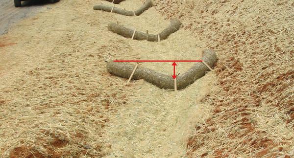
Figure 3. Make sure that the FCD fits snugly into the ditch contour with no gaps and a clear lower, center weir section (see the red arrow) set in the FCD large enough to withstand the storm event as designed.
Figure 4. Example of how to install FCDs by stapling them to the ground through the netting on both sides. Staples have not been fully inserted into the soil in order to see their placement.

Figure 5. An FCD with integral wings placed tightly in the ditch perpendicular to water flow with an erosion control blanket lining. Upslope-angled stakes and metal sod staples secure the FCD to the ground. Staples not hammered into the soil are visible.
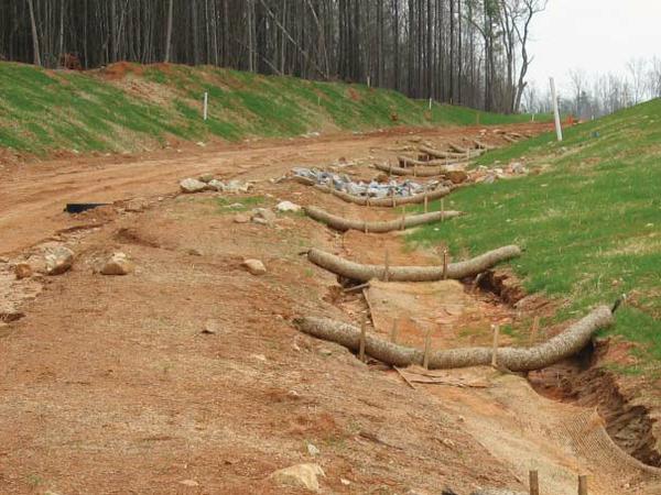
Figure 6. An example of improperly installed FCDs and ditch liner. The liner was not extended up the sides of the ditch, and the FCDs were not stapled into the ground. As a result, erosion occurred under the FCDs on the edges of the liner.
Maintenance
Remove sediment that accumulates behind FCDs when it reaches half the height of the device. Replace the FCD if it is damaged during sediment removal, as well as any FCDs that appear to be decomposing. Coir FCDs tend to degrade much more slowly than other natural fiber FCDs and should be used when the check dams will be in place for more than 3 or 4 months. FCD removal is usually not necessary at the end of the construction period unless the area will be a high-maintenance landscape such as a lawn or a commercial property.
Turbidity Reduction
The FCD system has been shown to reduce erosion and improve water quality in channels. However, the smaller and lighter silts and clays (.05 to .002 mm) are likely to remain in suspension and create too much turbidity. One approach to removing turbidity is to treat the water with polyacrylamide applied to the FCDs.
Polyacrylamide (PAM) is a water-soluble, synthetic polymer that acts as a highly effective binding agent with fine silts and clays. These particles are bound together with PAM to form flocs, which can settle out of the water to significantly reduce turbidity. This process is described in more detail in Soil Facts AG-439-62 (see reference section). Granular PAM is applied to the FCDs at the center weir point (Figure 7). Apply 2 to 4 ounces (1⁄4 to 1⁄2 cup) to each FCD. During the next runoff event, the PAM will partially dissolve and bind to the fibers, and will also begin releasing PAM into the runoff to flocculate the suspended sediment. Do not over apply as this may result in PAM being released in pieces before it can dissolve and becoming buried in sediment further downslope or in the sediment basin below. The PAM mixes with the runoff as water passes over each dam, improving flocculation efficiency. Once exposed to rainfall and runoff, the granular material forms a gelatinous pad that will slowly release PAM into the water flowing over the FCD. Reapply PAM at the same rate when it can no longer be observed on the FCD, either because it fully dissolved or it is covered with sediment.
Polyacrylamide-treated runoff should be directed into a sediment basin or similar device prior to discharge to effectively trap the flocculated material. If there is no device at the end of the ditch, the last few FCDs should not be treated with PAM so that they will trap the resulting flocs. There are many types and formulations of PAM, so make sure your supplier or manufacturer provides one that works for your soil. The North Carolina Division of Energy, Mineral and Land Resources has a list of PAMs approved for treating water.
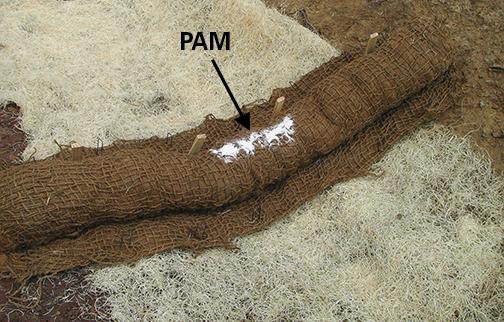
Figure 7. For improved turbidity reduction, the periodic addition of approximately 2 to 4 ounces of an appropriate granular PAM to the FCD is highly recommended.
Summary
Construction site ditches can be transformed from sediment sources to areas for sediment retention and turbidity reduction by using a system of FCDs and PAM. Careful attention to the design and installation will result in less sediment in the sediment basins and discharges with much less turbidity. This system can save money and reduce construction site impacts on nearby surface waters.
Reference
McLaughlin, R. A. SoilFacts: Chemical Treatment to Control Turbidity on Construction Sites. AG-439-62.
Publication date: March 10, 2015
Reviewed/Revised: March 28, 2025
AG-439-71
N.C. Cooperative Extension prohibits discrimination and harassment regardless of age, color, disability, family and marital status, gender identity, national origin, political beliefs, race, religion, sex (including pregnancy), sexual orientation and veteran status.