
The hose drag waste application system that broadcasts wastewater over the ground has gained popularity in North Carolina, and it offers several advantages over traditional irrigation and wastewater injection systems. Depending on the current system used, hose drag systems may reduce odor, make more nitrogen available to the plants, decrease compaction, increase management flexibility, and/or save time. While the hose drag system can be expensive, contractors offer hose drag waste application as a service. Operators should carefully consider all their options for land application of liquid manure and municipal and industrial wastewater and then choose the system that is most appropriate for their operations.
A hose drag system uses a hose to transport wastewater or sludge from a storage unit to an application unit normally pulled by a tractor. Wastewater1 may be injected or surface broadcast with such units. The application unit has a manifold, or distribution box, that sends the wastewater to individual discharge units mounted on a tool bar or frame 1 to 2 feet above the ground. The number of discharge locations depends on the width of the unit. The discharge unit may simply have flex tubing discharging against splash plates, or it may have tubing connected to hooded discharge points. In operation, the multiple outlet points combine to discharge a thin curtain of wastewater. Figure 1 and Figure 2 show the manifold and discharge points for hooded and splash plate configurations, respectively. Immediately in front of the discharge points are aeration tines, or knives, that help wastewater infiltrate the soil. The tines may be set to different “toe-in” angles to control degree of soil fracturing. Depth of penetration depends on soil type and the weight of the hose drag unit; the maximum depth achievable is usually about 8 inches. Weights added to the frame of the unit may aid tine penetration. Concrete blocks or 55-gallon drums filled with water can serve as weights. Figure 3 shows tine gangs, and Figure 4 shows an aerated surface. Since these units apply wastewater close to the ground using aeration, they are suitable for forage crops or for wastewater application prior to planting row crops. While the rate of application is very high, the short duration of application and the effect of aeration help prevent ponding and runoff. As with any wastewater application system, prevailing soil moisture and weather conditions should be within the guidelines given for wastewater irrigation in the wastewater application permit.
The application unit is typically connected to a hard hose and reel normally used with a traveling gun. Instead of connecting to a gun cart, the hard hose is mated to a swivel pipe on the application unit. A swivel pipe is shown in Figure 5. The application unit and attached hose is pulled by a tractor. Unlike hard hose traveling gun systems, pressure at the discharge point is very low, normally just a few pounds per square inch (psi), while the discharge rate is much higher than for a gun, exceeding 1,000 gallons per minute for the larger systems. Although only a few psi of pressure is required at the distribution box, inadequate pressure will result in uneven distribution among the outlet points. A ring may be inserted into the distribution box to raise the pressure in the box by partially blocking the outlets.
In some systems, a flex hose is used instead of a hard hose. This allows for a longer line than on a hard hose traveler; however, pulling a flex hose requires more horsepower than pulling a hard hose. It also typically requires an additional tractor, with operator, to operate a pulley or spool to help guide the flex hose, and to ensure that the tractor pulling the application unit is not pulling too much flex hose at any given time. This operation is referred to as “humping” the hose. Figure 6 shows one tractor in the mobile pulley system.
Hose drag systems have many advantages for wastewater application. Due to the higher discharge rates, wastewater can be applied more quickly than with a hard hose traveler. This can be an advantage when repeated rains limit application opportunities. Since the time required to apply a given volume of water is reduced, energy costs of pumping are reduced. Because wastewater is applied at a low height under low pressure, there is very little drift and applications can be done on days when other systems like traveling guns should not be used. Hose drag systems minimize odor problems compared to spray irrigation systems. Because the system is towed by a tractor, portions of waste application fields not wetted by a traveler due to lane layout constraints may be available for land application. Any change in wettable acreage must be accompanied by a change in the certified waste management plan.
Disadvantages of hose drag systems include the capital cost of the system (relative to a gun and gun cart that it might replace), plus the requirement of a tractor and tractor operator. Systems cost from about $9,000 for the 8-foot units to over $20,000 for the 20-foot units. If the system will replace a gun cart on a hard hose traveler, a different pump may be required since hose drag systems operate at much higher flow rates than a big gun. Due to cost, contractors operate many of these systems as a service. Because of the low height of these systems, use is limited to forage crops, small grain crops at early growth stages, and preplant applications on crops, such as corn and cotton.
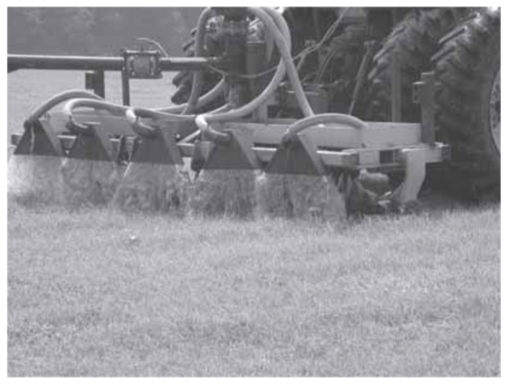
Figure 1. A typical hose drag type wastewater application unit with hooded outlets in operation.
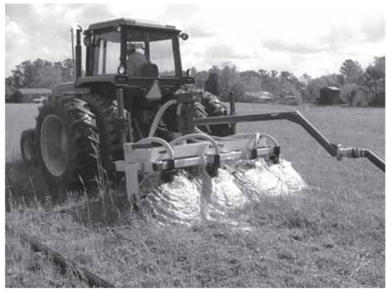
Figure 2. Hose drag application unit with splash plate outlets.
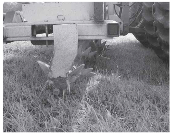
Figure 3. Aeration unit showing tines (knives). Tines are mounted on axles immediately in front of wastewater discharge points.
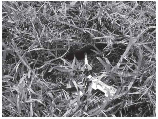
Figure 4. Hole made by aeration unit tine. Depth varies, with a maximum of about 8 inches.
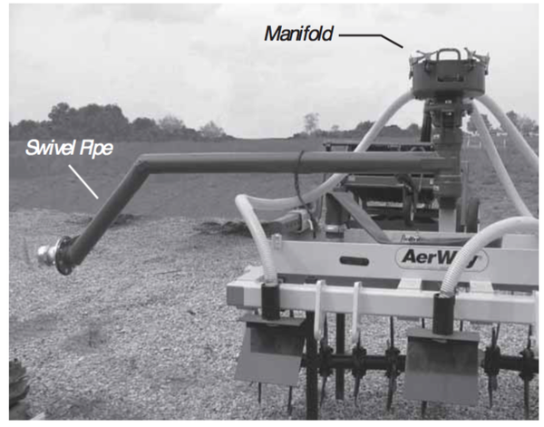
Figure 5. Swivel pipe and manifold for hose drag system.
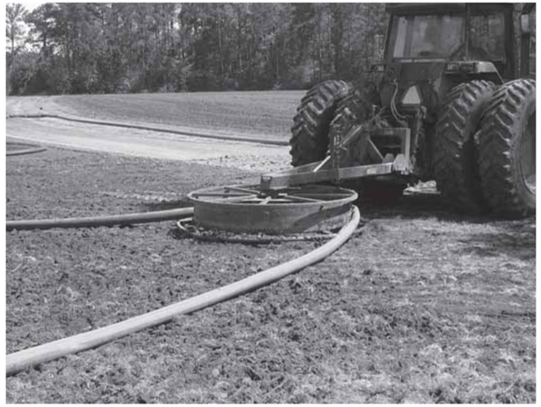
Figure 6. Pulley used to guide flex hose in the mobile pulley system.
Agronomic Impacts
Aerating a manure application may increase crop yield and nutrient uptake by the crop in compacted fields (e.g., intensively grazed pastures) with heavy (clayey) soils. In light or medium soils with little mechanical or animal traffic, aeration may not improve yield or nutrient uptake, and in some instances, it may be detrimental due to root damage. Hose drag systems may reduce ammonia losses, thereby increasing PAN values of the applied wastewater.
Water Quality Impacts
There are no published studies on the water quality impacts of hose drag systems, with or without aeration. Results of one study where liquid dairy manure was applied after aeration suggest that aeration may reduce nitrogen and phosphorus losses, but may also increase sediment loss (Shah, et al., 2004). The study also found no consistent reduction in runoff with aeration. Aeration may increase infiltration and reduce runoff in heavy soils that are compacted; this may also reduce losses of nutrients in runoff. The impact of aeration on groundwater quality has not been investigated.
Runoff potential depends upon discharge rate, tractor speed, field slope, soil type, soil moisture, and crop condition. The hose drag system operator should evaluate these factors to prevent runoff and potential water quality problems.
Air Quality Impacts
While there have been no controlled studies comparing the hose drag-aerator with big gun or center pivot systems, it is likely that the hose drag-aerator system reduces ammonia losses and odor. The wastewater is released closer to the ground in the hose drag method than in the center pivot, and particularly, the big gun. Shorter duration of exposure of the effluent to the air and lower operating pressure (larger drop sizes) may reduce transfer of ammonia and odor to the air compared to irrigation systems. Assuming that ammonia losses from hose drag systems described here are comparable to splash plates (or broadcasting), based on information from MWPS Manure Management Systems Series, Section 3: Air Quality (2002), it may be reasonable to assume that nitrogen losses with the hose drag would be 10 to 25 percent compared with 15 to 40 percent from sprinkler irrigation. While the aerator is expected to increase infiltration and thereby reduce the amount of ammonia or odor available for loss into the surroundings, there are no studies that compare ammonia losses or odor from the hose drag with or without the aerator.
Operation
The hose from a hard hose traveler is connected to a transitional flexible hose, approximately 10 feet in length, which in turn is connected to a rigid swivel pipe serving the manifold. Connectors are usually cam-lock type. In some cases, flex hose may be used to connect the unit directly to a pump rather than running it through an existing mainline and traveler. This is done primarily to reduce supply line length, thereby reducing friction loss and increasing flow. The flex tubing should be approximately the same inside diameter as the hard hose. The swivel pipe prevents kinking of the hose. Some units have a double swivel pipe having two hinges that allow tighter turns. With a double swivel pipe, transitional flexible hose is not required. A flow meter may be placed either in-line between a hydrant and the traveler intake, or on the application unit. A flow meter is shown in Figure 7. Flow meters placed at the hydrant are normally used only periodically to calibrate the systems and can be a propeller-type meter costing between $800 and $900. Flow meters dedicated to the application unit are subject to more exposure and are typically magnetic-type meters, costing $4,000-$5,000; they are more accurate and can provide instant feedback to the operator in the tractor.
The tines that aerate the ground immediately before wastewater application may be adjusted to provide different levels of aggressiveness. This is accomplished by setting the tines to different angles relative to the direction of travel. The least aggressive setting is with the tine axles set 90 degrees to the direction of travel. More aggressive settings provide for greater soil fracturing and potential wastewater storage, but they are more damaging to crop roots and may increase sediment loss.
The hose and unit should be pulled out to the most remote part of the field. This may be done with the hard hose empty or full. If pulling the hose out full, the operator should begin driving the tractor at the required speed after the system has been charged and wastewater begins to flow from the discharge points. Initially pulling the unit and hard hose to the most remote part of the field allows for the required slack as the unit is dragged back and forth in the field. The recommended travel pattern is shown in Figure 8. Care should be taken when turning to ensure that the tractor is not stay stationary for long. Most systems do not have a way to reduce or stop discharge, and with their high discharge rates stopping or slowing could lead to ponding and runoff. Turns are normally done in a three- point fashion in order to start adjacent to the last pass. The aerator unit is raised while turning to allow a sharper turn. Proper overlap is desirable to provide uniform application. The outside discharge points between any two adjacent passes should be the same distance apart as the discharge points along the aeration unit. Although the wetted width is slightly greater than the width of the hose drag units, proper overlap will result in an effective width approximately the same as the advertised width of the unit.
When fields are moderately wet or have a moderate slope, aerating the periphery of the application field prior to wastewater application will help prevent runoff. As with all cases, land application should only be done when runoff or extended periods of ponding are not likely to occur. Check current regulations in the wastewater application permit on allowable surface ponding duration.
The depth of the wastewater applied is controlled by tractor speed and discharge rate. Normally, for any given pump and reel combination, the discharge rate will be constant, and adjusting the tractor speed will adjust application depth. Pump speed may also be used to control application rate and depth if the pump is variable speed. Tables 1 through 5 show application depths for various tractor speeds, flow rates, and application unit widths.
The applications depths found in Table 1 are calculated from equation 1:
The effective width is the distance between the centerlines of adjacent passes of the unit. The widths given in Tables 1 through 5 are the advertised sizes of the hose drag systems, and can normally be used as the effective width.
The tractor speed required to apply a target depth when system flow rate is known can be determined by rearranging equation 1 to:
Application depths up to 1.0 inch are shown in Tables 1 through 5 because depths as great as 1.0 inch are given in some waste utilization plans; however, it is recommended that no more than 0.75 inches be applied during any given application. Limits set by individual waste utilization plans and existing soil moisture conditions will determine appropriate application depths. The depths shown in Tables 1 through 5 may be converted to gallons per acre by multiplying application depth by 27,154.
The average application depth over the entire field may be obtained from beginning and ending flow meter readings and the area irrigated. Flow rates used in the tables should be read only after the hose has filled and the flow rate has stabilized.
Flow rates for hose drag-type systems depend on the pump, mainline diameter and length, hose diameter and length, and the size and number of discharge points on the application unit. Flow rates from hose drag systems can exceed 1,000 gallons per minute for the larger units. Hose drag systems may require different pumps than those used with hard hose traveling gun systems, since they are designed to operate at much higher flow rates.
| discharge (gpm) | Tractor Speed (mph) | |||||||
|---|---|---|---|---|---|---|---|---|
| 0.5 | 1 | 1.5 | 2 | 2.5 | 3 | 3.5 | 4 | |
| 200 | 0.91 | 0.46 | 0.30 | 0.23 | 0.18 | 0.15 | 0.13 | 0.11 |
| 225 | 0.51 | 0.34 | 0.26 | 0.21 | 0.17 | 0.15 | 0.13 | |
| 250 | 0.57 | 0.38 | 0.28 | 0.23 | 0.19 | 0.16 | 0.14 | |
| 275 | 0.63 | 0.42 | 0.31 | 0.25 | 0.21 | 0.18 | 0.16 | |
| 300 | 0.68 | 0.46 | 0.34 | 0.27 | 0.23 | 0.20 | 0.17 | |
| 325 | 0.74 | 0.49 | 0.37 | 0.30 | 0.25 | 0.21 | 0.19 | |
| 350 | 0.80 | 0.53 | 0.40 | 0.32 | 0.27 | 0.23 | 0.20 | |
| 375 | 0.85 | 0.57 | 0.43 | 0.34 | 0.28 | 0.24 | 0.21 | |
| 400 | 0.91 | 0.61 | 0.46 | 0.36 | 0.30 | 0.26 | 0.23 | |
| 425 | 0.97 | 0.65 | 0.48 | 0.39 | 0.32 | 0.28 | 0.24 | |
| 450 | 0.68 | 0.51 | 0.41 | 0.34 | 0.29 | 0.26 | ||
| 475 | 0.72 | 0.54 | 0.43 | 0.36 | 0.31 | 0.27 | ||
| 500 | 0.76 | 0.57 | 0.46 | 0.38 | 0.33 | 0.28 | ||
| 525 | 0.80 | 0.60 | 0.48 | 0.40 | 0.34 | 0.30 | ||
| 550 | 0.84 | 0.63 | 0.50 | 0.42 | 0.36 | 0.31 | ||
| 575 | 0.87 | 0.66 | 0.52 | 0.44 | 0.37 | 0.33 | ||
| 600 | 0.91 | 0.68 | 0.55 | 0.46 | 0.39 | 0.34 | ||
| 625 | 0.95 | 0.71 | 0.57 | 0.47 | 0.41 | 0.36 | ||
| 650 | 0.99 | 0.74 | 0.59 | 0.49 | 0.42 | 0.37 | ||
| 675 | 0.77 | 0.62 | 0.51 | 0.44 | 0.38 | |||
| 700 | 0.80 | 0.64 | 0.53 | 0.46 | 0.40 | |||
| 725 | 0.83 | 0.66 | 0.55 | 0.47 | 0.41 | |||
| 750 | 0.85 | 0.68 | 0.57 | 0.49 | 0.43 | |||
| 775 | 0.88 | 0.71 | 0.59 | 0.50 | 0.44 | |||
| 800 | 0.91 | 0.73 | 0.61 | 0.52 | 0.46 | |||
| 825 | 0.94 | 0.75 | 0.63 | 0.54 | 0.47 | |||
| 850 | 0.97 | 0.77 | 0.65 | 0.55 | 0.48 | |||
| 875 | 1.00 | 0.80 | 0.66 | 0.57 | 0.50 | |||
| 900 | 0.82 | 0.68 | 0.59 | 0.51 | ||||
| Note: To obtain gallons per acre, multiply application depth (inches) in table by 27,154. Application depths to 1.00 inch are shown but applications greater than 0.75 inch are not recommended. | ||||||||
| discharge (gpm) | Tractor Speed (mph) | |||||||
|---|---|---|---|---|---|---|---|---|
| 0.5 | 1 | 1.5 | 2 | 2.5 | 3 | 3.5 | 4 | |
| 200 | 0.73 | 0.36 | 0.24 | 0.18 | 0.15 | 0.12 | 0.10 | 0.09 |
| 225 | 0.82 | 0.41 | 0.27 | 0.21 | 0.16 | 0.14 | 0.12 | 0.10 |
| 250 | 0.91 | 0.46 | 0.30 | 0.23 | 0.18 | 0.15 | 0.13 | 0.11 |
| 275 | 1.00 | 0.50 | 0.33 | 0.25 | 0.20 | 0.17 | 0.14 | 0.13 |
| 300 | 0.55 | 0.36 | 0.27 | 0.22 | 0.18 | 0.16 | 0.14 | |
| 325 | 0.59 | 0.39 | 0.30 | 0.24 | 0.20 | 0.17 | 0.15 | |
| 350 | 0.64 | 0.43 | 0.32 | 0.26 | 0.21 | 0.18 | 0.16 | |
| 375 | 0.68 | 0.46 | 0.34 | 0.27 | 0.23 | 0.20 | 0.17 | |
| 400 | 0.73 | 0.49 | 0.36 | 0.29 | 0.24 | 0.21 | 0.18 | |
| 425 | 0.77 | 0.52 | 0.39 | 0.31 | 0.26 | 0.22 | 0.19 | |
| 450 | 0.82 | 0.55 | 0.41 | 0.33 | 0.27 | 0.23 | 0.21 | |
| 475 | 0.87 | 0.58 | 0.43 | 0.35 | 0.29 | 0.25 | 0.22 | |
| 500 | 0.91 | 0.61 | 0.46 | 0.36 | 0.30 | 0.26 | 0.23 | |
| 525 | 0.96 | 0.64 | 0.48 | 0.38 | 0.32 | 0.27 | 0.24 | |
| 550 | 1.00 | 0.67 | 0.50 | 0.40 | 0.33 | 0.29 | 0.25 | |
| 575 | 0.70 | 0.52 | 0.42 | 0.35 | 0.30 | 0.26 | ||
| 600 | 0.73 | 0.55 | 0.44 | 0.36 | 0.31 | 0.27 | ||
| 625 | 0.76 | 0.57 | 0.46 | 0.38 | 0.33 | 0.28 | ||
| 650 | 0.79 | 0.59 | 0.47 | 0.39 | 0.34 | 0.30 | ||
| 675 | 0.82 | 0.62 | 0.49 | 0.41 | 0.35 | 0.31 | ||
| 700 | 0.85 | 0.64 | 0.51 | 0.43 | 0.36 | 0.32 | ||
| 725 | 0.88 | 0.66 | 0.53 | 0.44 | 0.38 | 0.33 | ||
| 750 | 0.91 | 0.68 | 0.55 | 0.46 | 0.39 | 0.34 | ||
| 775 | 0.94 | 0.71 | 0.57 | 0.47 | 0.40 | 0.35 | ||
| 800 | 0.97 | 0.73 | 0.58 | 0.49 | 0.42 | 0.36 | ||
| 825 | 1.00 | 0.75 | 0.60 | 0.50 | 0.43 | 0.38 | ||
| 850 | 0.77 | 0.62 | 0.52 | 0.44 | 0.39 | |||
| 875 | 0.80 | 0.64 | 0.53 | 0.46 | 0.40 | |||
| 900 | 0.82 | 0.66 | 0.55 | 0.47 | 0.41 | |||
| Note: To obtain gallons per acre, multiply application depth (inches) in table by 27,154. Application depths to 1.00 inch are shown but applications greater than 0.75 inch are not recommended. | ||||||||
| discharge (gpm) | Tractor Speed (mph) | |||||||
|---|---|---|---|---|---|---|---|---|
| 0.5 | 1 | 1.5 | 2 | 2.5 | 3 | 3.5 | 4 | |
| 300 | 0.91 | 0.46 | 0.30 | 0.23 | 0.18 | 0.15 | 0.13 | 0.11 |
| 325 | 0.99 | 0.49 | 0.33 | 0.25 | 0.20 | 0.16 | 0.14 | 0.12 |
| 350 | 0.53 | 0.35 | 0.27 | 0.21 | 0.18 | 0.15 | 0.13 | |
| 375 | 0.57 | 0.38 | 0.28 | 0.23 | 0.19 | 0.16 | 0.14 | |
| 400 | 0.61 | 0.41 | 0.30 | 0.24 | 0.20 | 0.17 | 0.15 | |
| 425 | 0.65 | 0.43 | 0.32 | 0.26 | 0.22 | 0.18 | 0.16 | |
| 450 | 0.68 | 0.46 | 0.34 | 0.27 | 0.23 | 0.20 | 0.17 | |
| 475 | 0.72 | 0.48 | 0.36 | 0.29 | 0.24 | 0.21 | 0.18 | |
| 500 | 0.76 | 0.51 | 0.38 | 0.30 | 0.25 | 0.22 | 0.19 | |
| 525 | 0.80 | 0.53 | 0.40 | 0.32 | 0.27 | 0.23 | 0.20 | |
| 550 | 0.84 | 0.56 | 0.42 | 0.33 | 0.28 | 0.24 | 0.21 | |
| 575 | 0.87 | 0.58 | 0.44 | 0.35 | 0.29 | 0.25 | 0.22 | |
| 600 | 0.91 | 0.61 | 0.46 | 0.36 | 0.30 | 0.26 | 0.23 | |
| 625 | 0.95 | 0.63 | 0.47 | 0.38 | 0.32 | 0.27 | 0.24 | |
| 650 | 0.99 | 0.66 | 0.49 | 0.39 | 0.33 | 0.28 | 0.25 | |
| 675 | 0.68 | 0.51 | 0.41 | 0.34 | 0.29 | 0.26 | ||
| 700 | 0.71 | 0.53 | 0.43 | 0.35 | 0.30 | 0.27 | ||
| 725 | 0.73 | 0.55 | 0.44 | 0.37 | 0.31 | 0.28 | ||
| 750 | 0.76 | 0.57 | 0.46 | 0.38 | 0.33 | 0.28 | ||
| 775 | 0.78 | 0.59 | 0.47 | 0.39 | 0.34 | 0.29 | ||
| 800 | 0.81 | 0.61 | 0.49 | 0.41 | 0.35 | 0.30 | ||
| 825 | 0.84 | 0.63 | 0.50 | 0.42 | 0.36 | 0.31 | ||
| 850 | 0.86 | 0.65 | 0.52 | 0.43 | 0.37 | 0.32 | ||
| 875 | 0.89 | 0.66 | 0.53 | 0.44 | 0.38 | 0.33 | ||
| 900 | 0.91 | 0.68 | 0.55 | 0.46 | 0.39 | 0.34 | ||
| 925 | 0.94 | 0.70 | 0.56 | 0.47 | 0.40 | 0.35 | ||
| 950 | 0.96 | 0.72 | 0.58 | 0.48 | 0.41 | 0.36 | ||
| 975 | 0.99 | 0.74 | 0.59 | 0.49 | 0.42 | 0.37 | ||
| 1000 | 0.76 | 0.61 | 0.51 | 0.43 | 0.38 | |||
| Note: To obtain gallons per acre, multiply application depth (inches) in table by 27,154. Application depths to 1.00 inch are shown but applications greater than 0.75 inch are not recommended. | ||||||||
| discharge (gpm) | Tractor Speed (mph) | |||||||
|---|---|---|---|---|---|---|---|---|
| 0.5 | 1 | 1.5 | 2 | 2.5 | 3 | 3.5 | 4 | |
| 300 | 0.73 | 0.36 | 0.24 | 0.18 | 0.15 | 0.12 | 0.10 | 0.09 |
| 325 | 0.79 | 0.39 | 0.26 | 0.20 | 0.16 | 0.13 | 0.11 | 0.10 |
| 350 | 0.85 | 0.43 | 0.28 | 0.21 | 0.17 | 0.14 | 0.12 | 0.11 |
| 375 | 0.91 | 0.46 | 0.30 | 0.23 | 0.18 | 0.15 | 0.13 | 0.11 |
| 400 | 0.97 | 0.49 | 0.32 | 0.24 | 0.19 | 0.16 | 0.14 | 0.12 |
| 425 | 0.52 | 0.34 | 0.26 | 0.21 | 0.17 | 0.15 | 0.13 | |
| 450 | 0.55 | 0.36 | 0.27 | 0.22 | 0.18 | 0.16 | 0.14 | |
| 475 | 0.58 | 0.38 | 0.29 | 0.23 | 0.19 | 0.16 | 0.14 | |
| 500 | 0.61 | 0.41 | 0.30 | 0.24 | 0.20 | 0.17 | 0.15 | |
| 525 | 0.64 | 0.43 | 0.32 | 0.26 | 0.21 | 0.18 | 0.16 | |
| 550 | 0.67 | 0.45 | 0.33 | 0.27 | 0.22 | 0.19 | 0.17 | |
| 575 | 0.70 | 0.47 | 0.35 | 0.28 | 0.23 | 0.20 | 0.17 | |
| 600 | 0.73 | 0.49 | 0.36 | 0.29 | 0.24 | 0.21 | 0.18 | |
| 625 | 0.76 | 0.51 | 0.38 | 0.30 | 0.25 | 0.22 | 0.19 | |
| 650 | 0.79 | 0.53 | 0.39 | 0.32 | 0.26 | 0.23 | 0.20 | |
| 675 | 0.82 | 0.55 | 0.41 | 0.33 | 0.27 | 0.23 | 0.21 | |
| 700 | 0.85 | 0.57 | 0.43 | 0.34 | 0.28 | 0.24 | 0.21 | |
| 725 | 0.88 | 0.59 | 0.44 | 0.35 | 0.29 | 0.25 | 0.22 | |
| 750 | 0.91 | 0.61 | 0.46 | 0.36 | 0.30 | 0.26 | 0.23 | |
| 775 | 0.94 | 0.63 | 0.47 | 0.38 | 0.31 | 0.27 | 0.24 | |
| 800 | 0.97 | 0.65 | 0.49 | 0.39 | 0.32 | 0.28 | 0.24 | |
| 825 | 1.00 | 0.67 | 0.50 | 0.40 | 0.33 | 0.29 | 0.25 | |
| 850 | 0.69 | 0.52 | 0.41 | 0.34 | 0.30 | 0.26 | ||
| 875 | 0.71 | 0.53 | 0.43 | 0.35 | 0.30 | 0.27 | ||
| 900 | 0.73 | 0.55 | 0.44 | 0.36 | 0.31 | 0.27 | ||
| 925 | 0.75 | 0.56 | 0.45 | 0.37 | 0.32 | 0.28 | ||
| 950 | 0.77 | 0.58 | 0.46 | 0.38 | 0.33 | 0.29 | ||
| 975 | 0.79 | 0.59 | 0.47 | 0.39 | 0.34 | 0.30 | ||
| 1000 | 0.81 | 0.61 | 0.49 | 0.41 | 0.35 | 0.30 | ||
| Note: To obtain gallons per acre, multiply application depth (inches) in table by 27,154. Application depths to 1.00 inch are shown but applications greater than 0.75 inch are not recommended. | ||||||||
| discharge (gpm) | Tractor Speed (mph) | |||||||
|---|---|---|---|---|---|---|---|---|
| 0.5 | 1 | 1.5 | 2 | 2.5 | 3 | 3.5 | 4 | |
| 500 | 0.91 | 0.46 | 0.30 | 0.23 | 0.18 | 0.15 | 0.13 | 0.11 |
| 525 | 0.96 | 0.48 | 0.32 | 0.24 | 0.19 | 0.16 | 0.14 | 0.12 |
| 550 | 1.00 | 0.50 | 0.33 | 0.25 | 0.20 | 0.17 | 0.14 | 0.13 |
| 575 | 0.52 | 0.35 | 0.26 | 0.21 | 0.17 | 0.15 | 0.13 | |
| 600 | 0.55 | 0.36 | 0.27 | 0.22 | 0.18 | 0.16 | 0.14 | |
| 625 | 0.57 | 0.38 | 0.28 | 0.23 | 0.19 | 0.16 | 0.14 | |
| 650 | 0.59 | 0.39 | 0.30 | 0.24 | 0.20 | 0.17 | 0.15 | |
| 675 | 0.62 | 0.41 | 0.31 | 0.25 | 0.21 | 0.18 | 0.15 | |
| 700 | 0.64 | 0.43 | 0.32 | 0.26 | 0.21 | 0.18 | 0.16 | |
| 725 | 0.66 | 0.44 | 0.33 | 0.26 | 0.22 | 0.19 | 0.17 | |
| 750 | 0.68 | 0.46 | 0.34 | 0.27 | 0.23 | 0.20 | 0.17 | |
| 775 | 0.71 | 0.47 | 0.35 | 0.28 | 0.24 | 0.20 | 0.18 | |
| 800 | 0.73 | 0.49 | 0.36 | 0.29 | 0.24 | 0.21 | 0.18 | |
| 825 | 0.75 | 0.50 | 0.38 | 0.30 | 0.25 | 0.21 | 0.19 | |
| 850 | 0.77 | 0.52 | 0.39 | 0.31 | 0.26 | 0.22 | 0.19 | |
| 875 | 0.80 | 0.53 | 0.40 | 0.32 | 0.27 | 0.23 | 0.20 | |
| 900 | 0.82 | 0.55 | 0.41 | 0.33 | 0.27 | 0.23 | 0.21 | |
| 925 | 0.84 | 0.56 | 0.42 | 0.34 | 0.28 | 0.24 | 0.21 | |
| 950 | 0.87 | 0.58 | 0.43 | 0.35 | 0.29 | 0.25 | 0.22 | |
| 975 | 0.89 | 0.59 | 0.44 | 0.36 | 0.30 | 0.25 | 0.22 | |
| 1000 | 0.91 | 0.61 | 0.46 | 0.36 | 0.30 | 0.26 | 0.23 | |
| 1025 | 0.93 | 0.62 | 0.47 | 0.37 | 0.31 | 0.27 | 0.23 | |
| 1050 | 0.96 | 0.64 | 0.48 | 0.38 | 0.32 | 0.27 | 0.24 | |
| 1075 | 0.98 | 0.65 | 0.49 | 0.39 | 0.33 | 0.28 | 0.24 | |
| 1100 | 1.00 | 0.67 | 0.50 | 0.40 | 0.33 | 0.29 | 0.25 | |
| 1125 | 0.68 | 0.51 | 0.41 | 0.34 | 0.29 | 0.26 | ||
| 1150 | 0.70 | 0.52 | 0.42 | 0.35 | 0.30 | 0.26 | ||
| 1175 | 0.71 | 0.54 | 0.43 | 0.36 | 0.31 | 0.27 | ||
| 1200 | 0.73 | 0.55 | 0.44 | 0.36 | 0.31 | 0.27 | ||
| Note: To obtain gallons per acre, multiply application depth (inches) in table by 27,154. Application depths to 1.00 inch are shown but applications greater than 0.75 inch are not recommended. | ||||||||
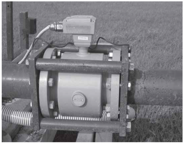
Figure 7. Magnetic-type flow meter mounted in-line on swivel pipe. Transducer with leads to tractor cab allows readout of flow rate.
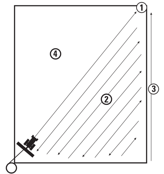
Figure 8. Traffic pattern for hose drag wastewater application: 1. drag hose to most remote part of field; 2. traverse back and forth abutting previous pass with appropriate overlap; 3. move back to far corner of field; 4. repeat procedure on other half.
Tractor Requirements
Tractor requirements are based on hose diameter, hose length, and size of the hose-drag unit. A tractor with at least 65 horsepower is required to draw the smaller units, which are typically matched with smaller hard hose travelers. Larger units may require tractors with 200 horsepower, especially if flexible hose used rather than hard hose. Four-wheel-drive tractors are preferable, especially on wetter fields or fields with moderate slopes.
Summary
Hose drag waste application systems provide an alternative to more traditional irrigation equipment and injection equipment. The high flow rates achievable with these systems allow for increased management flexibility compared to most irrigation equipment, and discharge close to the ground offers odor reduction compared to spray irrigation. Decreased ammonia volatilization is likely and would mean a potential increase in plant available nitrogen (PAN). Compared to tanker systems, hose drag systems result in less compaction and time savings. If using existing pumps and reels, care should be taken to be sure that they are matched with the hose drag system such that adequate flow is provided and proper uniformity is achieved.
References
2002. MWPS Manure Management Systems Series, Section 3: Air Quality. Livestock waste facilities handbook, MWPS18. Iowa State University.
Shah, S.B., J.L. Miller, and T.J. Basden. 2004. Mechanical aeration and liquid dairy manure application impacts on grassland runoff water quality and yield. Transactions of the ASAE 47(3):777-788.
Publication date: Jan. 1, 2005
AG-634
The use of brand names in this publication does not imply endorsement by NC State University or N.C. A&T State University of the products or services named nor discrimination against similar products or services not mentioned.
N.C. Cooperative Extension prohibits discrimination and harassment regardless of age, color, disability, family and marital status, gender identity, national origin, political beliefs, race, religion, sex (including pregnancy), sexual orientation and veteran status.