
Just as water naturally tends to flow downhill, heat naturally tends to travel from hot to cool. A refrigeration system is a machine that moves heat uphill from warm to hot. In this way, a refrigeration system is very much like a pump that moves water uphill against a pressure head. Properly sizing a pump requires knowing two things. First, you must know the flow, which is the amount of water you will be moving per unit of time (flow = amount/time). For example, gallons per hour would be a suitable unit for describing the flow of water moved by a pump. Second, you must know the height of the head or lift (resistance) against which the pump will operate. The units of lift could be feet, inches, meters, or any similar unit of linear measure. When the value of flow is multiplied by the value of the head, the result is power. By knowing flow and head, you can easily select a pump that is suitable for the job.
For example, with a pump raising 1000 gal of water per minute against a 10 ft head:
Work = (force) (distance) = (8.34 lb/gal) (1000 gal) (10 ft) = 83,400 ft-lb
Power = Work/time = (83,400) ÷ (1 min) or 2.53 horsepower is required
(One horsepower = 33,000 ft-lb/min)
The same is true for a refrigeration system that is a heat pump. The head or lift is similar to the difference in temperature (∆T) between the inside of the refrigerated space and the ambient temperature outside. The calculation of ∆T is rather simple. For a cooler with its inside temperature held steady at 45°F and the outside ambient temperature held steady at 90°F, the ∆T = 90 – 45 = 45 F°.
The units for ∆T are F°, not °F. A temperature of 45°F means something fundamentally different from “45 F°” (45 Fahrenheit degrees).
How do we know the refrigeration has been properly sized?
The important but often overlooked notion in sizing a refrigeration system is the concept of “held steady.” This means that a properly sized refrigeration system will generally hold the refrigerated space steady at the target temperature despite having loads of heat added from time to time. The loading of heat (such as hot produce) may cause the temperature of the refrigerated space to momentarily spike despite the large capacity of the system. If the refrigeration system has sufficient capacity, the time when the spike lasts will be relative short. The shorter the duration of the temperature spike, the more quickly the produce will be cooled because the rate of heat transfer is governed by the difference in temperature. In contrast, an oversized refrigeration system wastes money on unused capacity. A system that is large enough with some flexibility should be the aim of the designer. Determining the amount of heat to be transferred per unit of time (refrigeration load) from a refrigerated space to the outside, while keeping the internal temperature steady, is an involved process that requires organization and forethought.
The proper sizing of a refrigeration system that will be the working heart of the facility is complex and is the job of the postharvest engineer. The refrigeration load includes four basic factors, which must be determined individually and then totaled: field heat, respiration heat, conduction heat, and service heat. The removal of field and respiration heat is the basic function of a refrigerated space. Conduction and service heat are related to the construction and use of the facility.
Field Heat. The primary function of a refrigerated space is lowering the temperature of the warm produce coming from the field to its optimal storage temperature. Ambient temperature varies with the time of day, as well from day to day. Since it is not known what the ambient temperature will be at any particular time, it is easier to select a temperature in the upper range of harvest season ambient. For midsummer, this is assumed to be 90°F or even 95°F, although cantaloupe and melons exposed to the mid-day summer sun have been known to pulp over 110°F.
The equation for determining the total amount of field heat to be removed is:
Qf = Total Field Heat = m·Cp (ΔT)
Where:
Qf = total field heat (Btu)
m = mass of the produce (lb)
Cp = specific heat (Btu/lb·F°)
(ΔT) = temperature difference (F°)
The equation for Qf contains no factor for time because Qf is the total amount of heat to be removed (work to be done) regardless of the time required to complete the work. The power necessary to do this work (qf) is dependent on how fast you want to do it so that qf = Qf/time. For example, if Qf = 250,000 Btu and we wish to remove it in five hours, then: qf = 250,000/5 = 50,000 Btu/hr. Since the refrigeration load (the power to move heat uphill) = work/time, we must specify the time required to remove this heat. Where do we find this time? How do we know how much time will be required to cool a pallet of boxed tomatoes, for example?
The many factors that influence the transfer of heat from produce make the accurate calculation of cooling times virtually impossible given only the physical characteristics of the cooling setup. This is the reason that there are no reliable published tables that provide the ⅞ cooling times for fruit and vegetables. Time data are obtained empirically in the same way as other physical characteristics that govern heat transfer. The options are finding published data with the cooling curve for a similar setup or conducting our own experiment. Experienced engineers often have personal records of field notes that were meticulously collected from past jobs and which can be used with similar types of produce.
In the example above, there is the assumption that the ⅞ cooling time is four hours instead of five hours. Then qf = 250,000/4 = 62,500 Btu/hr. Thus, it would require a refrigeration system 25% larger (and more expensive) to accomplish the cooling in the less time (62,500/50,000 = 1.25). The reverse is also true in that allowing more time for cooling will require a marginally small unit. The time will have a profound effect on the refrigeration load and the size (and cost) of the required refrigeration system. If the selected refrigeration system can maintain a steady room temperature, the size of the refrigeration system is irrelevant to the time required to cool the produce. The factors that limit the cooling time are related to the physical properties of the particular cooling setup such as size, shape, packaging, and airflow.
Unscrupulous refrigeration contractors have been known to specify units far larger than necessary with the false promise that the large units will cool the produce more quickly. As long as the refrigeration system can hold the temperature at the specified temperature, the capacity of the system is not related to cooling time. The limiting factor is the heat transfer from the produce to the air. More is not always better.
Respiration Heat. All fresh produce is alive and respiring as living cells carry out their life functions. This is simply the chemical oxidation of carbohydrates into energy, water, and carbon dioxide. The rate of energy production in terms of Btu/hr is a function of both the temperature (Arrhenius effect) and the type of tissue. The equation for the production of respiration heat is:
qr = m · r
Where:
qr = respiration heat generation (Btu/hr)
m = mass of the produce (lb)
r = rate of heat production (Btu/lb/hr)
The USDA Handbook 66 provides the rate of respiration heat production for most types of fresh produce as a function of temperature. Since the produce enters the refrigerated space warm and leaves cool, what temperature and corresponding rate of heat production should you use in your calculations? The respiration heat values are an estimated average of those at field ambient and optimal storage temperature and are generally sufficient for most purposes when calculating respiration heat.
As an example, suppose you have 1250 lb of sweet corn. r = .757 Btu/lb·hr. Then: qr = (1250) (0.757) = 946 Btu/hr.
The heat produced per hour at warm temperatures will be considerably greater than the heat produced as the produce approaches the optimum storage temperature. Averaged over the length of cooling time, there is a steady output of .757 Btu/lb·hr.
Conduction Heat. A source of parasitic heat in a refrigerated space is the heat that is conducted continually through the roof, walls, and floor. This will occur as long as there is a temperature difference (∆T). Refrigerated spaces are similar to a leaking boat. When pumps do not continually remove the leaking water from the boat, the boat will eventually sink. If the refrigeration system does not remove the heat leaking into the refrigerated space, the temperature on the inside will eventually be the same as outside (∆T = 0).
The steady flow of heat through a surface with a constant temperature difference between one side and the other depends on three partially independent processes:
- The transfer of heat to the wall from the surrounding air on the hot side (convection)
- The transfer through the wall (conduction)
- The transfer of heat to the air from the wall on the cold side (convection)
There is some heat transfer by radiation but it is minor compared to the heat transferred by conduction and is ignored.
The equation for heat transfer via conduction is straightforward. In practice, the calculation of conduction heat is complicated by the variations in thermal resistance of the different types and thickness of construction materials, the exposure to radiation (sunlight), and the surface area. Each discrete area must be calculated separately and then summed to yield the total conduction load. The basic equation for heat conduction through a planar surface is:
q = UAΔT
Where:
q = heat flow through the section (Btu/hr.)
U = overall heat transfer coefficient [Btu/(ft2·hr·F°)]
A = area (ft2)
ΔT = temperature difference across section (F°)
The concepts and determinations of “A” and “∆T” are simple, although the overall heat transfer coefficient “U” requires a more detailed explanation. The overall heat transfer coefficient, “U”, is a measure of the conduction through a given section. The term “overall” represents a sum of both the conduction and convection of each component of the wall section. For this reason, it is often referred to as “Utotal.”
Utotal = 1/(1/hi + x1/k1 + x2/k2 + x3/k3 + …..… +1/ho)
Where:
hi = inside surface conductance, [Btu/(ft2·hr·F°)]
ho = outside surface conductance, [Btu/(ft2·hr·F°)]
xn = thickness of particular section, (in)
kn = thermal conductivity of section, [Btu · in/(ft·hr·F°)]
The total resistance to heat flow through the wall is the sum of the resistance of the wall itself (conductive heat transfer) and the two resistances between the surfaces of the wall and their respective surroundings (convective heat transfer). For a composite wall that contains several insulation materials, the heat transfer is calculated through each and then summed into the total. In common usage, an upper case “R” denotes the thermal resistance of the entire section regardless of thickness materials, where a lower case r denotes the thermal resistance per inch of thickness. For example, a four-inch thick section of polystyrene may have an R-factor of 24 but an “r” factor of 6.
| "Material" | "r-value per in. (ft2·°F·h/(BTU·in))" |
|---|---|
| "Polyurethane rigid panel (CFC/HCFC expanded) initial" | "7.0–8.0" |
| "Polyurethane rigid panel (CFC/HCFC expanded) aged 5–10 years" | "6.25" |
| "Polyurethane rigid panel, initial" | "6.8" |
| "Polyurethane rigid panel, aged 5–10 years" | "5.5" |
| "Foil-faced polyisocyanurate rigid panel, initial" | "6.8" |
| "Foil-faced polyisocyanurate rigid panel aged 5–10 years" | "5.5" |
| "Polyisocyanurate spray foam" | "4.3 – 8.3" |
| "Closed-cell polyurethane spray foam" | "5.5 – 6.5" |
| "Phenolic spray foam" | "4.8 – 7.0" |
| "Urea-formaldehyde panels" | "5.0 – 6.0" |
| "Urea foam" | "5.25" |
| "Extruded expanded polystyrene (XPS) high-density" | "5.0 – 5.4" |
| "Polystyrene board" | "5.0" |
| "Phenolic rigid panel" | "4.0 – 5.0" |
| "Urea-formaldehyde foam" | "4.0 – 4.6" |
| "High-density fiberglass batts" | "3.6 – 5.0" |
| "Extruded expanded polystyrene (XPS) low-density" | "3.6 – 4.7" |
| "Icynene loose-fill (pour fill)" | "4.0" |
| "Molded expanded polystyrene (EPS) high-density" | "4.2" |
| "Rice hulls" | "3.0" |
| "Fiberglass batts" | "3.1 – 4.3" |
| "Molded expanded polystyrene (EPS) low-density" | "3.85" |
| "Icynene spray" | "3.6" |
| "Open-cell polyurethane spray foam" | "3.6" |
| "Cardboard" | "3.0 – 4.0" |
| "Rock and slag wool batts" | "3.0 – 3.85" |
| "Cellulose loose-fill" | "3.0 – 3.8" |
| "Cellulose wet-spray" | "3.0 –3.8" |
| "Rock and slag wool loose-fill" | "2.5 – 3.7" |
| "Fiberglass loose-fill" | "2.5 – 3.7" |
| "Polyethylene foam" | "3.0" |
| "Cementitious foam" | "2.0 – 3.9" |
| "Perlite loose-fill" | "2.7" |
| "Wood panels, such as sheathing" | "2.5" |
| "Fiberglass rigid panel" | "2.5" |
| "Vermiculite loose-fill" | "2.1 – 2.4" |
| "Vermiculite" | "2.13" |
| "Straw bale" | "1.45" |
| "Softwood (most) " | "1.4" |
| "Wood chips and other loose-fill wood products" | "1.0" |
| "Hardwood (most) " | "0.7" |
| "Brick" | "0.2" |
| "Glass" | "0.14" |
| "Poured concrete" | "0.08" |
Since conductance and resistance are reciprocals, Utotal = 1/Rtotal or Rtotal = 1/Utotal
A Useful Analogy
In electrical circuits:
I = V/R,
Where:
I = the flow of current (analogous in the case above with the flow of heat, q)
V = the voltage potential or ∆V between ground and V (analogous to ∆T)
R = the resistance to flow (analogous to 1/(U·A)
Likewise, the flow of heat, q, is equivalent to a potential, ∆T times the area, A, divided by a resistance, R = 1/(U·A)
q = UAΔT
The heat conduction per unit time into a refrigerated space, qc, is the sum of the heat conduction through all the surrounding surfaces:
qc = qwalls + qroof + qfloor
When possible, the refrigerated space should approach a cube to maximize the enclosed volume with the least enclosing area. When circumstances allow, height should be maximized. It is always less expensive to build up than to build out.
Walls and Roof
The walls and roof constitute the majority of the surface area that encloses a refrigerated space. In the past, different building materials were used such as wood, metal, and concrete block with various types of insulation. In recent years, metal sheathing and fiber or rigid foam insulation are used, as shown in Figure 5-1.
Compared to older construction materials, metal buildings are more durable, better insulated, less expensive, and capable of being built in a shorter period of time. With modern metal buildings, there is considerable flexibility in the type and color of the inside and outside sheathing. For refrigerated spaces, white or a very light color are best for reflecting heat. This includes the roof. It is good practice to limit the southern exposure (long side on the east and west sides). South walls are exposed to the sun throughout the day, east and west walls for part of the day, and north walls for short period of time. The roof receives sunlight all day. Since sun exposure can increase the temperature of exposed surfaces, it is good practice to increase the ∆T by 50 F° above the difference between the inside and outside.
The calculation of wall surface is simply the sum of the areas (length × height) of all exterior wall surfaces. Typically, there is the question about what area to consider for the roof. Most modern metal buildings have relatively flat (<1/12) pitch so that the roof area can be considered essentially equal to the floor area. For buildings with a steeper pitch roof, it is customary to install an insulated ceiling equal in height to the height of the wall (known as the eve height). The volume above the ceiling, with its large, exposed roof area, is not refrigerated but may be ventilated to reduce the temperature. Without ventilation, these areas can easily reach temperatures 50 F° or more above ambient. The ceiling area then becomes the roof area and is equal to the floor area.

Figure 5-1. Wall section of modern insulated metal building.
Source: M. Boyette.

Figure 5-2. Determining the ∆T for different surfaces. Exterior surface temperature depends on orientation, color, surface, wind, and other factors.
Source: M. Boyette.
Floors
On a square foot basis, floors are far more expensive to build than walls or roofs. With grading, forming, reinforcement, insulation, drains, utilities, anchor bolts, and six or more inches of concrete, the cost of flooring is a major portion of the total building cost. Concrete is a rather poor insulator. On the positive side, the heat transfer through the floor is normally less than the walls or roof. Soil temperature remains remarkably steady throughout the year. In most areas of the upper south, the mean soil temperature ranges from 58°F to 62°F, although it can be as low as 40°F in the upper mid-west to 75°F in the deep south.
The need for insulation under the concrete is questionable. If the temperature of the refrigerated space is close to the ground temperature, it is difficult to justify the cost of insulation. A good example is a sweetpotato storage room where the optimum storage temperature is 58°F. If the ground temperature is also about 58°F, no heat transfer will occur and no insulation is needed. As the room temperature moves higher than the ground temperature, the added cost of insulation becomes more justified. To determine if under floor insulation is justified, the cost of insulation must be compared to the cost of the added refrigeration capacity in terms of fixed and operating cost over the life of the building. Unfortunately, insulation cannot be added after the floor is poured. Fortunately, the cost of insulation is relatively small. If heat transfer through the floor is an issue, now or in the future, it is wise to consider insulation during building construction.
In addition, insulation is required to prevent ground heave when the temperature of the refrigerated space is expected to be below freezing for extended periods. Ground heave occurs when saturated soil freezes and then expands. This expansion can break floors and foundation walls and can destroy the integrity of the building. Floor heaving may only be remedied by removing the original floor and re-pouring the concrete over adequate insulation. This is difficult and expensive.
The best type of insulation for under a floor is rigid, polystyrene closed-cell foam that is designed with a crush strength sufficient to support over one ft of concrete plus the design load of the floor (see Figure 5-3). This is also an excellent vapor barrier that prevents soil moisture from migrating to the floor’s upper surface. The insulation is typically sold in 4 ft by 8 ft sheets that are available in various thicknesses. As shown in Table 5-1, the insulation has an r-factor of 5 (ft2·°F·h/(BTU·in.)).
Service Heat. Service heat is a broad category of heat that may enter the refrigerated space. The amount of service heat in terms of Btu/hr depends on how the space will be used. The introduction of service heat varies over the course of a day from zero to nearly ½ of the total heat load from all sources. The service heat load may be the combined heat from some or all the following:
Outside Air Infiltration
The contribution to the service heat load from outside air infiltration is difficult to obtain and is very dependent on the difference between the conditions of the air inside the room to the ambient air. For example, warm moist air that enters a refrigerated space is a larger load than the same volume of cool dry air. The size of the doors and the length of time they remain open are also important. The heat load from a walk-in door opened for only a few seconds is minor compared to a large roll-up or sliding door that is large enough for a lift truck. The size of the lift truck door should be kept to a minimum. The general rule is to specify a door width that is only 1 to 1½ times wider than the widest item likely to pass through the door. In a busy facility, it is inconvenient to open and close large doors each time a vehicle passes through the door. To decrease the infiltration of air and also allow free access, most large doors are now equipped with transparent strip curtains as shown in Figure 5-4.
The ASHRAE Handbook on Refrigeration has several equations to calculate the heat transfer from open doors. These equations rely on estimates of doorway open time, flow factor, and the effectiveness of protective devices such as strip curtains. In general, however, it is more convenient to simply add a certain percent to the total of the field, respiration, and conduction loads:
- For rooms that are accessed infrequently through a walk-in door only, add 0% to 1%.
- For rooms used primarily for long-term storage that are entered infrequently through a large door with a strip curtain, add 1% to 3%.
- For rooms with large doors with a strip curtain that are entered multiple times per day, add 4% to 6%.
- For rooms with large doors with strip curtains that remain open for extended periods, add 8% to 10%.
With reach-in coolers such as home refrigerators and display cases in stores, air infiltration may contribute as much as 50% to the total refrigeration load.
Lighting
Cold storage facilities are considered mixed use or warehouse facilities. At the present time, the US Occupational Safety and Health Administration (OSHA) does not have standards for general warehouse lighting. The agency states, however, that overhead lighting should be “adequate for the task at hand” to promote proper ergonomics and safety. State and local authorities, as well as insurance companies, may have separate rules that govern lighting in such facilities. The basic fact is that all the electric power supplied to a refrigerated space will eventually turn to heat.
Fortunately, the efficiency of lighting has increased in last 30 years. In comparison, most of the electrical power (>90%) used by incandescent lights was wasted as heat. Modern LED bulbs produce very little heat, require about 1/6 the power to produce the same amount of light, and have a longer service life.
Before calculating the service heat from lighting and other electrical equipment inside the refrigerated space, it is important to understand the concept of duty cycle. Most of the electrical equipment in refrigerated rooms such as lights, fans, and humidifiers do not operate on a continuous basis. For example, the lights should be on only when someone is working in the room. If that time is estimated at an average of 15 minutes per hour, then the duty cycle, D, for the lights is 15/60 = .25 ➔ 25%. If the fans on the evaporator coils only operate a total of 20 min per hour, then their duty cycle would be 33%. If the forced-air cooling fans operate continually, their duty cycle is 100%.
The calculation of service heat from lighting is very straight forward. This is the total wattage of all lights times the duty cycle times the conversion factor: (0.293 Btu/W·hr)
ql = 0.293 n · W · D
Where:
ql = heat load from lighting, (Btu/hr)
n = the total number of lights in the space
W = the wattage of each light assuming they are all the same
D = duty cycle
Fans and Humidifiers
Electrically operated equipment such as fans and humidifiers are treated essentially the same as lights. The operating wattage is customarily found on the equipment nameplate. For fans and other items with electric motors, the nameplate horse power can be converted to Btu/hr: (1 hp = 2544 Btu/hr):
qf = 0.293 n · hp · D
Where:
qf = heat load from fans and humidifiers (Btu/hr)
n = the total number of items in the space
hp = the horse power of each item assuming they are all the same
D = duty cycle
In forced-air cooling facilities, the fans used to move the air through the produce can be a major source of service heat. For example, a forced-air cooling room with six lanes, each with a 1 hp fan can add (6) (2544) = 15,264 Btu/hr of heat to the room. This will require over 1¼ tons of additional refrigeration to overcome. It is often tempting to increase the fan hp in order to increase the air flow and reduce cooling time. However, since heat conduction from the produce may be the limiting factor, an increase in air flow (increasing the convection coefficient) may have little effect on the cooling time but a large effect on capital and operation costs. This means paying the power company to power the fans and the lights, and then paying the company again for power to supply the refrigeration system to remove the excess heat.
Forklifts
The contribution of forklifts to the total service load heat is often difficult to determine but should not be ignored. In enclosed areas such as refrigerated rooms, electric forklifts are preferred over liquefied petroleum (LP) gas operated units.
Published data suggests that a typical electric forklift may produce 1/10 the wasted heat output compared to an internal combustion forklift of comparable size (2500 Btu/hr versus 25,000 Btu/hr).
Emissions from LP gas forklifts are much cleaner than gasoline or diesel fueled units, but they also produce substantial amounts of CO2, CO, nitrogen oxides, and trace amounts of ethylene. Only trace amounts of ethylene are required to hasten ripening and senescence in susceptible fruit and vegetables.
qfl = (2544) · hp. · D
Where:
qfl = heat load generated from a forklift (Btu/hr)
hp = the horse power rating of the forklift (1 hp = 2544 Btu/hr)
D = duty cycle
People
The amount of heat generated by an individual depends on the temperature inside the room and the individual’s level of activity. Data published by ASHRAE includes:
| Refrigerated Space Temperature | Heat Generated by Each Person |
|---|---|
| 60°F | 716 Btu/hr |
| 40°F | 818 Btu/hr |
| 32°F | 921 Btu/hr |
| 23°F | 1023 Btu/hr |
| 14°F | 1125 Btu/hr |
| 5°F | 1228 Btu/hr |
| -4°F | 1330 Btu/hr |
In most cases, the heat produced by a person is ignored if they spend little time in the refrigerated space. The infiltration from going in and out may be greater than the heat given off by the person while inside. There are situations, however, where packing and processing is done in a refrigerated space. In these cases, the total heat of a work group should be counted. The duty cycle is the portion of an hour a person remains in the refrigerated room.
Latent Heat Load
One of the most insidious forms of service heat is the condensation of water on the cooling coils. In the relatively high humidity environment of most produce cooling and storage facilities, water condenses on the cooling coils because the temperature of the coils is below the dew point of the air. For example, if the dry bulb temperature inside a refrigerated room is 40°F and the relative humidity is 90%, the dew point temperature is 37°F. Any surface below the dew point temperature will collect condensation. For the refrigeration system to maintain the temperature at 40°F, the temperature of the cooling coils must be below 40°F. How much below is a critical design factor.
This type of heat load is insidious because the water is collected on a drip pan on the bottom of the coil housing and discretely piped out of the building to some inconspicuous place. (See Figure 5-5.) Ideally, the volume of water should be very small but under certain conditions, this can amount to several gallons per hour. Refrigeration capacity that is used to condense water is refrigeration capacity that is not available to cool produce. For example, given that the heat of condensation for water is 970 Btu/lb, the condensation of three gallons of water per hour requires:
(3 gallons) (8.34 lb/gallon) (970 Btu/lb) = 24,269 Btu/hr
This is over two tons of refrigeration capacity that is wasted. In addition, because the coils are removing water from the air, the humidity is lowered below the optimum, which then requires an additional humidifier to replace the lost humidity.
For most fresh produce, maintaining the humidity at 85% to 90% is essential to maintain quality. Cooling coils naturally remove moisture from the air. Consider these two cooling coils:
- Coil 1 is rated at 100,000 Btu/hr with dimensions of 36 in. tall by 72 in. wide by 6 in. thick.
- Coil 2 is also rated at 100,000 Btu/hr but has dimensions of 24 in. tall by 48 in. wide by 4 in. thick.
Coil 1 is much larger than Coil 2 and has a far greater heat exchange area than Coil 2. For both coils to be rated the same Btu/hr, the air exiting from Coil 2 must be colder than the air exiting from Coil 1. This can only occur if Coil 2 is colder than Coil 1. The colder the coil, the greater the condensation. The difference in the temperature of the air entering the cooling coil and the air leaving is known as ∆T. (Do not confuse this ∆T with the difference between ambient and the temperature of the refrigerated space.) Consequently, in addition to being rated at Btu/hr, refrigeration coils are also rated at Btu/∆TF°. Table 5.3 shows an approximate relationship between relative humidity and ∆T in forced convection.
| Relative Humidity % | Coil ∆T, F° |
|---|---|
| 95 – 91 | 8 – 10 |
| 90 – 86 | 10 - 12 |
| 85 – 81 | 12 – 14 |
| 80 – 76 | 14 – 16 |
| 75 – 70 | 16 – 18 |
Source: Clark, J. P. 2012. “Principles of Refrigeration.” Institute of Food Technologists. p. 243.
Summing the Load Components
After the field, respiration, conduction, and service heats have all been determined individually, the values should be summed to yield the total heat load of the facility in terms of Btu/hr. If your calculations yielded the following:
Field heat load = 158,500 Btu/hr
Respiration heat load = 4,500 Btu/hr
Conduction heat load = 24,000 Btu/hr
Service load = 11,000 Btu/hr
Total = 198,000 Btu/hr
Then calculate the percentages each contributes to the total.
Field heat load ➔ 80%
Respiration heat load ➔ 2.3%
Conduction heat load ➔12.1%
Service load ➔ 5.6%
Total ➔ 100%
The sum of the field and respiration heat is 82.3% of the total. The removal of the field and respiration heat is the purpose of the facility and should be the largest portion of the total load. As a general rule, the sum of the field and respiration heat should be 80% or more. The conduction and service heat are parasitic and contribute nothing to the postharvest quality of the produce.
Calculating the percentages is a good method to determine if the amount of insulation is sufficient. For example, if the conduction heat load is above 20%, it would be wise to add more insulation to the design and then re-calculate the numbers. Given the finite life of the facility, at some point the cost of additional insulation will not be justified by the additional savings of equipment and energy costs. Thus, the payback period of the insulation will exceed the life of the facility. The same might pertain to attempts to reduce the service heat load. After moving from an LP gas to an electric forklift and adding strip doors, further attempts to reduce the service load may not be justified economically.
If at this point we are satisfied with the percentages, then continuing with the example above, we have calculated the total heat load to be 198,000 Btu/hr. Since the capacity of refrigeration systems is rated in tons (one ton of refrigeration = 12,000 Btu/hr) then:
(198,000 Btu/hr) / (12,000 Btu/hr/ton) = 16.5 tons
Thus, a refrigeration system rated at 16.5 tons should be able to adequately maintain the target temperature and displace all the heat load. However, this allows for no flexibility or safety factors. Under peak load, a system would be operating continually, which would exacerbate wear and maintenance issues. By convention, we apply a duty cycle to the whole system of 75%. In this case, the calculated tonnage is divided by .75. This provides a cushion or safety factor. Now the proper system capacity is:
16.5 tons/.75 = 22 tons
It is likely that a 22 ton capacity system would be available for commercial use. But what if only 10 or 12 tons were required for extended periods during the cooling season? Would it make any sense to split the 22 tons into two systems with a 10 ton and a 12 ton unit? How does the installed cost of two small systems compare to one large system? What about electrical costs? If only 10 tons were required, would it be less expensive for electrical power to operate a 12 ton system than a 22 ton system operating at less than half capacity? And, what if the single 22 ton system malfunctioned? Now no cooling is available. If the load were split between two units and one broke down, there would be some partial cooling still available from the other one. These are all questions that should be considered by the prudent engineer in collaboration with the equipment suppliers and the facility’s owner.
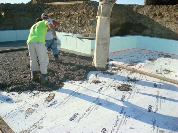
Figure 5-3. Pouring a concrete floor over rigid polystyrene foam board insulation.
Source: M. Boyette.

Figure 5-4. Large door equipped with transparent strip curtains.
Source: M. Boyette.

Figure 5-5. Drip pan and drain under refrigeration coils.
Source: M. Boyette.
Calculation of Refrigeration Load
Being a consulting engineer can be both rewarding and lucrative for the engineer with the proper training and a good business sense. Suppose you, as a consulting postharvest engineer, have been contracted to design a forced-air cooling facility for a packer/shipper of mixed produce. How would you start? What question will you need to ask?
The design of a postharvest cooling facility is a complex undertaking and must be conducted in a very organized, methodical way. The engineer’s raw material is information. In addition to the structural components (roof, floor, and walls), a major component is the refrigeration system. The structural design of a building is important and usually the responsibility of the building contractor. However, a produce handling facility is more than a building. A good way to envision a postharvest facility is a complex arrangement of equipment surrounded by a building.
The major rule of postharvest engineering is that each type of produce has its own postharvest requirements. The task would be simple if the same amounts of the same produce came in and out each day and all the different items could be placed into the same room under the same conditions for temperature, humidity, and ethylene. However, this is rarely the case. The proper sizing of the refrigeration load is straightforward when considering heat transfer. However, the complication is the variable nature of the different types of produce and the uncertain nature of the throughput. Throughput describes the amount of produce that is expected to be cooled and/or stored over a certain period of time. Day-to-day variations in the amount and timing of harvests, coupled with the variations in timing of shipments out of the facility, can make the determination of a design cooling load and storage space very challenging. Estimating how much produce is received each day is a function of how many acres are planted, the yield, and unpredictable factors such as weather, rainfall, and the availability of labor and machines.
It is essential to have a good understanding of throughput over the course of the harvest season. It is helpful to create a spreadsheet or table as shown in Table 5.4 that shows the types and anticipated amounts (in number of full pallets) of produce per day that are likely during the harvest season. These numbers are estimates. It would be helpful to add a safety factor to ensure adequate working capacity.
| Item | 7/8 Cooling Time (hr) | Net Pallet Weight (lb) | Week 1 | Week 2 | Week 3 | Week 4 | Week 5 | Week 6 | Week 7 | Week 8 |
|---|---|---|---|---|---|---|---|---|---|---|
| Cantaloupe | 8 | 700 | 5 | 7 | 10 | 12 | 14 | 12 | 8 | 6 |
| Tomatoes | 5 | 500 | 0 | 6 | 8 | 16 | 18 | 14 | 10 | 5 |
| Peppers | 4 | 280 | 0 | 6 | 10 | 8 | 8 | 4 | 0 | 0 |
| Cucumbers | 3 | 425 | 0 | 6 | 16 | 28 | 30 | 16 | 8 | 0 |
| Sweet corn | 8 | 725 | 0 | 7 | 18 | 20 | 18 | 10 | 0 | 0 |
| Squash | 6 | 375 | 0 | 12 | 15 | 15 | 9 | 7 | 5 | 0 |
Source: M. Boyette.
The pallet weight for different items varies considerably. However, for determining space in a forced-air cooling lane, pallet racks, or refrigerated truck, a pallet is a pallet and is considered a “space” or footprint. A pallet is just another form of produce packaging. Pallets have a foot print of roughly by 42 in. by 48 in. and are generally 6 ft to 7 ft tall. Produce pallets are not double stacked two high.
Getting Started
The raw material of engineering is information. Make every effort to obtain all the information you can. Take notes and photos and keep them in the project file for frequent reference. Question everyone involved in the operation of a cooling facility that is similar to the one you will design. The people who are engaged in the day-to-day operation of a facility will always know the small nuances and techniques that make the operation run smoothly. It is wise to always ask these individuals what not to do. Be careful not to repeat other engineers’ mistakes. With the information you gather and important information from reference publications (such as ASHRAE, USDA, and HB-66), you are now ready to design the facility. Remember to be organized and stay organized. There are many inter-related parts that can have a significant influence on the overall design. Overlooking a small but critical point can be very difficult to remedy after the facility is built.
Considerations
Here are items you should consider during the design process:
- Make a list of all your knowns and assumptions.
- Make sure your estimated throughput is accurate, current, and considers how throughput might change in subsequent years as the business grows or the mix of crops changes in response to demand.
- Determine the physical size of the cooling facility (the refrigerated space for active cooling and cold storage), as well as the space needed for packing equipment, box storage, and loading docks. The unrefrigerated space may not have a direct impact on the sizing of the refrigeration system, but is still part of the process. Throughput includes what is received and what is shipped. There must be enough space for storage when shipping is delayed. It is always better to store produce in the same room where the produce is cooled, although this might not be possible. Since forklift time in and out of a refrigerated space adds significantly to the service load, the decision about storage requires judgment. When produce items will only be held for a day, you may ignore restrictions about humidity, ethylene, and odor transfer.
- Determine if more than one room is required based on the specific cooling and storage requirements of different types of produce. Having a dedicated room for each individual produce is often not physically or financially feasible. Holding produce a few degrees above the optimum temperature may only have a negligible effect on shelf life.
- It is acceptable to assume a 5-degree grace above but not below the optimum temperature. This means is that if one produce item has an optimum storage temp of 40°F and another item has an optimum temperature of 45°F, it is acceptable to put both produce items in a 45°F room but not to put them both in a 40°F room.
- For simplicity, assume that all produce has been loaded into the room at the same time.
- The active cooling time (the time the forced-air cooling fans are running continually) is the same as the ⅞ cooling times.
- Determine how many forced-air cooling lanes are required. It is safe to assume that one lane will accommodate 24 pallets. (Cooling lanes are 10 ft by 72 ft.)
- The temperature of any cooling room may be adjusted to any temperature from 36°F and above.
- Assume that the forced-air cooling fans all have 1½ hp motors. Most items will not require that much air flow but with variable frequency drives (VFD), the horsepower and airflow can be lowered. Cutting airflow back by one-half reduces the power consumption by 87.5%.
- You should make a floor plan at scale of your cooler design and any associated storage and handling space.
- Specify the appropriate R-factor for the insulation for the walls, ceiling, and floor.
- Assume a ceiling height of 12 ft. The ceiling may be higher if pallet racks are used, although 12 ft is acceptable for a room used for forced-air cooling with pallet heights of no more than 7 ft. This allows enough room to suspend the cooling coils from the ceiling.
- Assume two individuals and one forklift truck will be going inside for a total of four hours per day. Identify if the forklift truck is electric or LP gas powered.
- Assume lighting power of 1 watt/ sq ft with a 25% duty cycle.
- Determine the maximum refrigeration load required based on the peak time of the year and the mix of produce at the time. Assume a 75% duty cycle on the refrigeration system.
- Remember to calculate the percentages.
Publication date: May 1, 2025
Other Publications in Introduction to the Postharvest Engineering for Fresh Fruits and Vegetables: A Practical Guide for Growers, Packers, Shippers, and Sellers
- Chapter 1. Introduction
- Chapter 2. Produce Cooling Basics
- Chapter 3a. Forced-Air Cooling
- Chapter 3b. Hydrocooling
- Chapter 3c. Cooling with Ice
- Chapter 3d. Vacuum Cooling
- Chapter 3e. Room Cooling
- Chapter 4. Review of Refrigeration
- Chapter 5. Refrigeration Load
- Chapter 6. Fans and Ventilation
- Chapter 7. The Postharvest Building
- Chapter 8. Harvesting and Handling Fresh Produce
- Chapter 9. Produce Packaging
- Chapter 10. Food Safety and Quality Standards in Postharvest
- Chapter 11. Food Safety
- Postscript — Data Collection and Analysis
N.C. Cooperative Extension prohibits discrimination and harassment regardless of age, color, disability, family and marital status, gender identity, national origin, political beliefs, race, religion, sex (including pregnancy), sexual orientation and veteran status.