Introduction
Many farmers are now considering dual-purpose subsurface systems that provide both drainage birrigation to minimize water-related stress on crops. During wet periods these systems provide drainage, removing excess water from the field through a network of underground tubing. During drought periods the drainage outlet can be managed to control the amount of drainage, and water can be piped into the system, if desired, for subirrigation. For a subirrigation system, one of the most impor tant factors to consider is the water supply. If supplemental water is not available, the system may still provide some benefit by simply controlling drainage outflow. However, in a system designed for both drainage and subirrigation, the drain lines are normally spaced closer together than in a system in tended for drainage only. This closer spacing, which increases the cost of the system, is of little benefit if an adequate water supply for subirrigation is not available. The amount of water actually required for subirrigation and the extent of benefits provided by either controlled drainage or subirrigation depends on the crop, soil, and local weather conditions.
How Much Water Is Enough?
During peak water-use periods, most crops will require up to ¼ inch of water per day. With traditional overhead irrigation systems, most of this water must be supplied by irrigation. To provide this amount, the water source must be able to deliver a continuous supply of 4.7 gallons per minute per acre (gpm/ac) just to satisfy the crop's water needs. When irrigation water losses – such as evaporation, leaks, and nonuniform application patterns – are considered, the required capacity is even greater. The design capacity normally recommended is 7 gpm/ac. A properly managed subirrigation system, on the other hand, can often supply crop water demands at capacities less than 7 gpm/ac because it can supply water to the root zone even if the water table recedes somewhat.
As the water table drops from 18 to 36 inches during dry periods, the soil above the water table provides from ½ to over 2 inches of water available to plants. This water is in addition to any amount provided through irrigation. If a limited supply of irrigation water – such as 3.5 gpm/ac – is available, this amount, when added to the water stored in the soil (1 inch, for example) could supply the crop's water needs (1/4 inch per day) for up to two weeks.
During prolonged dry periods, the water table will eventually drop too low for the soil to supply any of the crop's water needs, and the capacity of the irrigation system's water supply must exceed the amount needed by the crop if drought stress is to be avoided. Thus it is very important to consider the probability that a critically long dry period will occur at a given location. This can best be accomplished using long term weather records in conjunction with DRAIN MOD, a computer program for calculating drainage and irrigation system requirements.
In many soils, seepage may result in significant water loss that must be replenished by the irrigation water supply. Seepage losses – the slow movement of water horizontally or vertically away from the area of the crop's roots – are very difficult to estimate. When possible it is best to try to eliminate them altogether.
Seepage may occur vertically or laterally, but vertical losses are normally small. For example, ground water recharge in many poorly drained areas of the coastal plain is less than 2 inches per year. This amount corresponds to about 1/200 of an inch per day, or less than 2 percent of the evapotranspiration rate during the irrigation season.
Lateral or horizontal seepage losses, on the other hand, can be quite large. Water can be lost by seepage to uncontrolled drainage ditches or to nonirrigated fields, especially when the ditch that supplies water for subirrigation adjoins nonirrigated areas such as a forest. In these cases, lateral seepage losses may con sume more than 25 percent of the pumping capacity. In some cases irrigation systems are installed in fields where randomly located tiles have been installed previously to drain trouble spots. These old tiles can also drain off large amounts of irrigation water if not adquately blocked or controlled.
Lateral seepage losses can be minimized with good planning, system layout, and management. Whenever possible, supply canals should be located near the center of irrigated fields rather than along one side. Perimeter ditches and outlet canals should also be equipped with control structures. Although subirrigation water might not be added to these ditches, controlling the drainage rate can significantly reduce seepage. The water level in the outlet ditch should be kept somewhat lower than in the irrigation ditch to ensure adequate drainage when heavy rain fall occurs. However, a 6- to 12-inch gradient from the field to the outlet ditch is much more desirable than a 4- to 6-foot gradient, which could be the case if the outlet is uncontrolled. Whenever possible, irrigated fields should be constructed in square blocks to minimize the length of the boundaries along which seepage could occur.
When the seepage loss cannot be controlled, the additional water capacity needed to overcome seepage losses must be estimated. Chapter 9 in the DRAIN MOD reference report, Methods for Design and Evaluation of Drainage-Water Management Systems for Soils with High Water Tables,* describes methods for estimating seepage losses under constant conditions.
It is necessary first to identify the location and size of the seepage boundary as well as the hydraulic gra dient and hydraulic conductivity along the boundary. Unfortunately, this is usually difficult. Several measurements may be required because the seepage zone is often composed of several layers of varying thickness and conductivity. When it is not possible or convenient to make these measurements, it is usually adequate to increase the water supply capaci ty by 25 to 30 percent to replace seepage losses. However, this additional capacity will cost money, and the potential savings that may be realized by obtaining a more accurate estimate will usually justify the time and effort required.
*R.W. Skaggs, 1980. Copies are available from SCS. Draft Technical Release. ↲
Types of Water Supplies
When planning an irrigation system, first attention should be given to the water source. Three aspects should be considered: location, quantity, and quali ty. When possible, the water supply should be located close to the area to be irrigated to reduce conveyance losses, pumping costs, and supply pipe cost. The prin cipal sources of irrigation water in North Carolina are ponds, rivers, streams, and wells. The source of water is not too important if enough water of good quality is available to meet the needs of the crop.
Ponds
Irrigation ponds are of two kinds: the impounded or earthen embankment type and the dug, or excavated, type. In North Carolina, the Soil Conservation Service (SCS) has provided assistance in constructing thousands of ponds. Many additional ponds have been constructed without assistance.
The impounded pond can be constructed in any location that has soil and topography suitable for construction of a dam. Impounded ponds are best suited to the upper coastal plain, piedmont, and mountain regions where the surface topography requires con struction of a dam on only one or two sides. Nearly all impounded ponds are supplied by surface runoff, with little or no recharge from groundwater. Thus, they must store enough water to meet crop needs during most of the irrigation season.
To find the capacity of an impounded pond, multiply the surface area by the average depth. Determining the average depth may be difficult unless a topographic map of the pond is available. One method is to multiply the pond's greatest depth by 0.4. Normally the pond will be deepest at the vertical stand pipe of the mechanical spillway that runs through the dam.
The acreage that can be irrigated from an impounded pond will depend on the number of times irrigation is required and the recharge rate of the pond. If the pond's rate of recharge from surface runoff or groundwater during the growing season is minimal and if a total of 6 inches of irrigation is required per acre, a storage capacity of 12 acre-inches per acre of cropland is recommended for farms in North Carolina.
If the pond is recharged by springs or a stream, the required storage capacity is less.
In North Carolina a permit is required to construct a pond that impounds more than 10 acre-feet of water and has a dam more than 15 feet high. Section IV of the SCS Technical Guide (code 378) gives minimum standards for the design and construction of ponds located in predominantly rural or agricultural areas. These are normally referred to as Class A ponds and have an embankment with a height of 35 feet or less. If such a dam should fail, it will result in damage only to farm buildings, agricultural land, or unimproved roads.
The Division of Environmental Management (DEM) of the North Carolina Department of Natural Resources and Community Development (NRCD) is responsible for the certification and inspection of dams in North Carolina. Subchapter 2K, "Dam Safety Regulations," issued by the EMC spells out the criteria for the design, construction, and inspection of dams. This general statute pertains to all dams that are more than 15 feet high and impound more than 10 acre-feet of water. Excluded are dams constructed by agencies of the United States government, such as the U.S. Army Corps of Engineers and the Tennessee Valley Authority.
In areas where the water table is naturally high, the dug (excavated) pond may be practical. These ponds normally store groundwater; very little recharge comes from surface waters. Excavated ponds are usually not very well suited for irrigating large acreages because they must occupy a large land area in order to store enough water to last through the entire irrigation season. In some instances, the pond may penetrate a shallow water-bearing sand layer capable of recharging the pond rapidly (within a few hours or days). However, it is very difficult to determine the recharge rate before the pond is constructed. Thus unless the pond is very large, it is quite likely that it will not recharge rapidly and will not be able to supply enough water. One alternative is to recharge the pond with small wells that penetrate a surficial aquifer.
Dug ponds are normally constructed with a drag line, a hydraulic excavator, a pan or scraper, or a track or rubber-tired tractor. The pond's width is nor mally 40 to 60 feet, but the length may vary from less than 100 feet to more than 1,000 feet. The construction cost normally ranges from 75 cents to $1.50 per cubic yard of storage capacity, depending on the distance the spoil must be transported. A typical dug pond with slow recharge and the capacity to irrigate 50 acres could cost more than $40,000.
Dug ponds are more expensive per gallon of water stored than impounded ponds. As the rate of recharge decreases, the storage capacity of a dug pond must be increased. If no recharge occurs during the irrigation season, the cost could exceed $800 per acre-foot of usable storage capacity. If the pond recharges rapidly, a dug pond may be less expensive per gallon of pumping capacity than an impounded pond.
On gently sloping low-lying areas, a combination dug and impounded pond may be practical. To construct such a pond, the spoil removed from the lowest areas is used to build a shallow dike or levee around the perimeter. Such ponds normally recharge from both surface runoff and shallow groundwater. The combined recharge rate is still rather slow, and since the pond is generally very shallow (less than 5 feet deep), it may consume a very large land area.
Some low-lying areas have been designated as wetland areas. In these locations it may be necessary to obtain a 404 permit from the Army Corps of Engineers before attempting any dredging or filling. However, constructing an irrigation reservoir in wetlands no longer requires a 404 permit. To ensure that no wetland regulations are violated, it is recom mended that the Corps of Engineers be consulted before dredging or filling in wet areas. Also, it may be necessary to obtain a state 401 Water Quality Certification from the Environmental Management Division of NRCD before installing an irrigation structure in wetlands. The purpose is to ensure that water quality will not be degraded by the irrigation ac tivities. The Coastal Area Management Act transfers jurisdiction of activities in tidal counties to the State of North Carolina, requiring a North Carolina 202 permit. If there is any question about the wetland status of an area, contact the Soil Conservation Service.
Streams
Streams can be another satisfactory source of water for irrigation. Often, however, a stream will be at its lowest level when the most irrigation water is needed. Other property owners may also be drawing irrigation water from the same stream, further reducing the flow. Since most of the water in a stream comes from surface runoff, it is a potential source of disease and pesticide contamination and should be tested before use.
Stream flow during a dry summer period should be measured before deciding to rely on the stream as the primary water source for irrigation. The stream capacity needed will depend on the number of hours that water will be pumped each week. For subirrigation systems, which can be operated continuously, a flow rate of 7 gallons per minute per irrigated acre will be sufficient. On the other hand, a traveling gun irrigation system operating only 50 hours per week and applying 2 acre-inches per week would require nearly 25 gallons per minute per irrigated acre. By placing a temporary dam across the stream to store some of the flow, the stream can be made to support more acreage.
The doctrine of riparian rights governs the use of stream water. This doctrine states that an owner of property bordering a stream can make reasonable use of the water but may not appreciably diminish the stream's flow. This regulation is incompatible with irrigation because in many cases constructing a low dam across the stream or diverting the stream into a reservoir for irrigation use will use almost the en tire stream flow.
Before pumping from a stream, local authorities should be contacted to ensure that no regulations will be violated. Some streams serve as a water supply for urban areas, and pumping irrigation water from them may not be allowed. In some areas local ordinances restrict the construction of dams across streams. Even though no permit is required to pump from a stream, any dredging or filling activity involving a stream requires a 404 permit from the Army Corps of Engineers because the area along the stream bank is usually wetland.
Wells
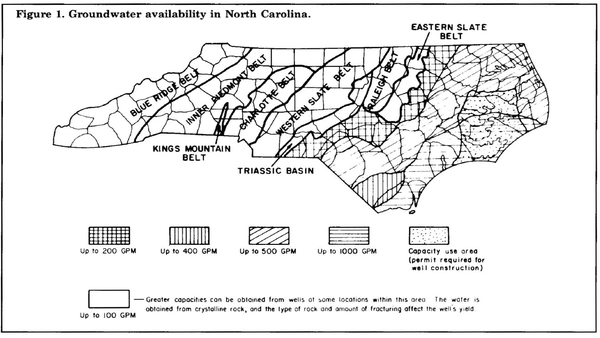
Groundwater in North Carolina is obtained from a variety of formations and aquifers. In the coastal plain, much of the area is covered by surficial sands that yield small quantities of water to driven, bored, dug, and jetted wells. Below the sands at depths of 50 to 300 feet is found the Yorktown aquifer, which supplies small quantities to domestic wells. The Pungo River aquifer, which provides moderate to good yields, is present in some eastern counties, but it has not been extensively developed. The Castle Hayne aquifer is by far the highest-yielding groundwater source in the coastal plain. Figure 1 provides an overall view of groundwater availability in North Carolina.
Depending upon the location within the state and the size and type of well, capacities up to 3,000 gallons per minute can be realized. Near the coast, wells can produce high yields, but the salinity may be high enough to render the water useless for irrigating crops. Westward from the Castle Hayne area, well yield decreases.
Before investing in a well for irrigation, contact local well drillers and groundwater hydrologists from the North Carolina Department of Natural Resources and Community Development (NRCD) for assistance. These hydrologists are located in district offices in Asheville, Fayetteville, Mooresville, Raleigh, Washington, Wilmington, and Winston-Salem. They have a good knowledge of groundwater conditions, and their services are available to individuals.
Publications on water quantity and quality have also been prepared by the United States Geological Survey in cooperation with NRCD. Some pertain to an area or region, others to particular counties, and still others to a portion of a county. Some of these reports are very detailed and are used by well drillers and others to predict the quantity and quality of groundwater that can be expected from a well.
Several types of wells can be constructed for irrigation. Their usefulness depends on the depth of the water to be used and the capacity needed. For irrigating a small acreage, a battery of small wells penetrating the surficial sands may be adequate. These wells are usually constructed by driving a well point attached to 1¼- to 2-inch pipe into the water bearing formation and are thus referred to as driven wells. The maximum depth for a driven well is about 50 feet. The yield from these wells is normally low (less than 10 gpm). A shallow-well jet pump is generally used to pump a single well, or one such unit may be used for several wells at the same time. A typical driven well 50 feet deep costs less than $500.
The jetted or washed-down well is constructed by using high-pressure water to force a well casing into the ground. The casing varies from 1¼ to 4 inches in diameter, and the maximum depth of the well is about 150 feet. This type of well is also normally constructed in soft, nonconsolidated sand sediments rather than rock formations. Because their yield is fairly low, a battery of wells may be needed. A shallow-well jet pump is normally used, but in larger diameter wells a deep-well jet pump can be installed. A typical jet ted well costs from $500 to $2,000.
Several types of deep irrigation wells can be con structed. Referred to as drilled wells, they are con structed with percussion or rotary equipment to depths of 1,000 feet or more. The normal depth, however, is 200 to 500 feet. A drilled well is normal ly cased with steel pipe (although PVC can be used) to the depth where it reaches rock. There are three types: the open-end tubular well, the tubular sand well, and the gravel-packed or developed well.
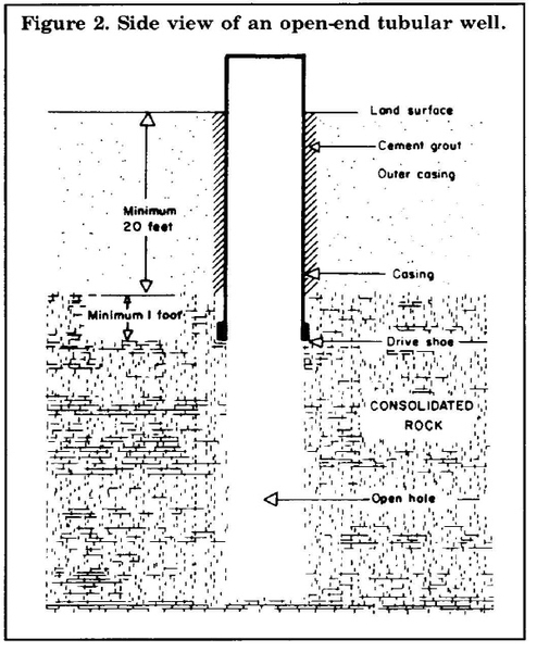
The open-end tubular well is normally used in rocky parent material, which is found mainly in the pied mont and western North Carolina. However, this type of well can be used in a few sections of the coastal plain – for example, in the area of the Castle Hayne limestone aquifer. The well is drilled into the rock and a steel or PVC casing is then driven into the rock. The end of the well is left open, as shown in Figure 2.
Since these wells are used in consolidated materials, the water comes from the cracks or fractures that develop in the rocks. Thus, the yield from open-end tubular wells is usually low – less than 300 gpm except in the Castle Hayne area.
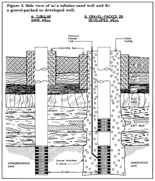
The second type of drilled well is the tubular sand well. These wells must be cased over their entire length, and inlet screens are used in the water bearing layers, as shown in Figure 3a. The sand well is used in nonhomogeneous unconsolidated sand. When water is first pumped from this type of well it contains a certain amount of sand because fine sand particles pass through the screen. With continued pumping, however, large sand grains lodge around the screened area and form a natural filter. A screen with a slot size of 0.01 to 0.06 inch is usually suffi cient to allow water to enter and keep most of the sand out, but it is advisable to select a screen size that will restrict the movement of the larger sand particles. The gravel-packed or developed well is used in homogeneous unconsolidated sand sediments. Because the sand particles in these sediments are of uniform size, they do not form a natural filter, and they continue to come through the screen. The space around the screen is therefore packed with gravel, which forms an artificial filter. To construct this type of well, the hole drilled is normally twice the diameter of the well casing, as shown in Figure 3b. The casing with appropriate screens is then put in place and gravel or sand of a variety of sizes is packed around the screen to form a filter that will allow water, but not sand, to enter.
It is very difficult to give a general cost estimate for deep wells because the cost varies with geographic location, type, size, depth, required yield, and whether or not the well driller is required to guarantee the yield. For assistance in choosing a well location and for more exact yield and cost estimates, contact ground water hydrologists from NRCD and local well drillers with experience in drilling irrigation wells in your area. A test well costing from $1,000 to several thousand dollars will provide a more reliable estimate of total well cost and yield for your location. The cost of some deep irrigation wells in stalled recently is given in Table 1.
Groundwater use in North Carolina is governed by The North Carolina Well Construction Act, State Statute Chapter 87, Article 7, Section 87. This act is administered by the Environmental Management Division of NRCD. The main objective of the statute is to protect goundwater resources to ensure that all users have an adequate supply of water. Protection is very important because once a groundwater source has been contaminated it takes many years to correct the problem.
The statute pertains mainly to the location of wells in relation to possible sources of pollution; well con struction standards, including the type of casing and the cementing of the casing; testing and disinfection; and identification of wells. The act was recently amended to require registration of all persons engaged in the business of constructing wells or installing or repairing pumps and other well equipment.
The statute requires that all wells be sealed from intrusion of surface water by encasing them with grout to a depth of 20 feet. An exception is made when water of potable quality cannot be found below 20 feet and it is therefore necessary to construct a shallower well between 10 and 20 feet deep. In such cases the grout must extend the length of the casing but under no circumstances less than 10 feet.
Driven wells and often jetted wells are installed by the landowner or user. Since a hole larger than the casing has not been provided, the well is not sealed by any means other than the contact between the soil and the pipe. With these wells there is greater probability of contamination from surface runoff seeping down the sides of the pipe. Trenching around the top of the pipe down to the first clay layer and backfilling with cement will reduce the likelihood of con tamination but will not eliminate it entirely because the distance from the surface to the water supply is not very long – often less than 20 feet. Great care should be taken to locate a driven or jetted well as far as possible from potential sources of contamination.
| County | Size of casing (inches) | Depth of casing (feet) | Estimated yield (gpm) | Power Source | Cost of pump and power unit | Well cost per foot | Total well cost |
Total water supply cost per gpm |
|---|---|---|---|---|---|---|---|---|
| Camden | 6 | 80 | 300 | PTO & DC generator | $ 2,500 | $25 | $2,000 | $15 |
| Halifax1 | 8 | 130 | 350 | 3-phase | 2,000 | 38 | 5,000 | 20 |
| Pamlico | 6 | 250 | 330 | 1-phase | 2,500 | 25 | 6,250 | 27 |
| Scotland | 8 | 110 | 350 | 3-phase | 4,000 | 59 | 6,500 | 30 |
| Washington | 16 | 280 | 2,000 | DC generator | 10,000 | 71 | 20,000 | 15 |
| Florence | 12 | 400 | 1,100 | Diesel with right-angle drive | $10,0002 | $125 | $50,000 | $55 |
1This amount does not include the $5,000 cost for installing three-phase service. ↲
2Includes cost of pump only. Diesel engine was salvaged from an old piece of machinery. ↲
Pumps and Power Units for Subirrigation
Types of Pumps
The pumps used for subirrigation systems are generally of either the centrifugal or propeller type. Centrifugal pumps include the volute type, which is used for irrigation systems when pumping water from surface sources and shallow wells, and the turbine type, which is used when pumping from deep wells. The centrifugal pump is a radial flow device, as shown in Figure 4. Water enters the center, or "eye," of the impeller and is thrown toward the outside. The water is captured by the volute, or casing, which is in the form of a spiral with a cross-sectional area that in creases toward the discharge opening. Three types of impellers can be used in centrifugal pumps: open, semi-enclosed, and enclosed; however, only the enclosed impeller is normally used for high-pressure irrigation pumps.
Centrifugal pumps may or may not be self-priming. The self-priming type can be recognized by its large casing. The pump will prime itself as long as the lower halfofthe casing above the eye of the impeller is fill ed with water (and provided that the suction head of the pump is not exceeded). Self-priming pumps have the suction port on the end and the discharge port at the top. A straight centrifugal pump is not self. priming and may have the suction port on the side or end. Most have a discharge port on the side, but in some high-pressure irrigation pumps it is located on the top.
The maximum theoretical suction lift or head of a centrifugal pump is 34 feet, but the practical maximum suction lift is about 20 feet. Centrifugal pumps are ideally suited for irrigation pumping. For each operating speed, they have a certain capacity and head. By varying the speed, a wide range of operating conditions can be obtained. The following rules govern variable-speed pumps:
-
The flow capacity (Q) varies directly with the impeller speed (RPM):
\(\frac{Q_2}{Q_1}=\frac{{\rm RPM}_2}{{\rm RPM}_1}\)
-
The total head (H) varies with the square of the speed:
\(\frac{H_2}{H_1}=\left(\frac{{\rm RPM}_2}{{\rm RPM}_1}\right)^2\)
-
The horsepower (HP) required to drive the pump varies with the cube of the speed:
\(\frac{{\rm HP}_2}{{\rm HP}_1}=\left(\frac{{\rm RPM}_2}{{\rm RPM}_1}\right)^3\)
Where it is not practical to change speeds — as, for example, when the pump is driven by an electric motor — the pumping capacity and head can be varied by changing the impeller size. The following relationships apply:
-
The capacity (Q) varies with the cube of the impeller diameter (D):
\(\frac{Q_2}{Q_1}=\left(\frac{D_2}{D_1}\right)^3\)
-
The head (H) varies with the square of the impeller diameter:
\(\frac{H_2}{H_1}=\left(\frac{D_2}{D_1}\right)^2\)
-
The horsepower (HP) varies with the fifth power of the impeller diameter:
\(\frac{{\rm HP}_2}{{\rm HP}_1}=\left(\frac{D_2}{D_1}\right)^5\)
These equations do not hold exactly for all pumps but are accurate enough to use in determining the pump size and capacity needed.
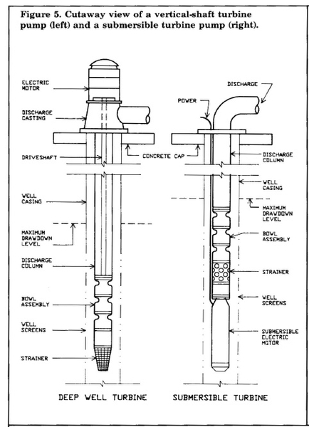
Turbine pumps, which include the vertical shaft turbine and the submersible type, are normally used for pumping from wells (Figure 5). The vertical turbine pump consists of a bowl assembly containing the impellers, driveshaft, discharge column, and discharge casting (pump head). The power source is an electric motor mounted on the pump head or an internal combustion engine connected through a right-angle drive. The bowl assembly is mounted in the well. To increase the head, several bowl assemblies (each referred to as a stage) may be used. When more than one bowl assembly is used, the head is additive for all the im pellers or stages.
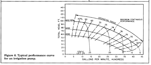
In the submersible pump, the electric motor is located at the bottom of the pump. The pump is sup ported by the drop pipe or discharge column through which water flows to the surface. The body and motor of the submersible pump and the bowl assembly of the turbine pump are located below the water level. Turbine pumps are generally more efficient than centrifugal pumps if operated at the speed for which they were designed, but they cannot operate at a high efficiency over as wide a range of speeds as centrifugal pumps. While no pump is 100 percent efficient, pump efficiencies as high as 85 to 90 percent are now at tainable. To minimize the operating cost, the most ef ficient pump possible should be selected. All pump manufacturers provide graphs similar to the one in Figure 6 to show the performance characteristics of their pumps.
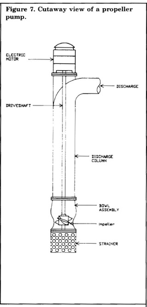
Propeller pumps are low-head, high-volume devices that can be used when pumping from a surface water supply with very little lift. As shown in Figure 7, the propeller is located in a housing, and water is driven in a direction parallel to the axis of the drive shaft. Propeller pumps are normally used when a head of less than 10 feet is required. They have usually been used for pumped drainage systems.
Power Units
Irrigation pumps may be driven by electric motors or internal combustion engines. Where electricity is available, it is the most economical power source, but in many rural areas electrical lines do not run close to the water source. In addition, three-phase power is often unavailable in these areas. Most electric com panies require three-phase power for electric motors that deliver more than 7.5 horsepower, although the size may vary from 5 to 10 horsepower depending on the application and the company providing the service. Because subirrigation systems operate at zero head once the water has been lifted to the surface, a 7.5 horsepower motor is normally sufficient if a sur face water source is available. On the other hand, if the water source is a deep well, the power required to lift the water will normally exceed 7.5 horsepower, thus requiring three-phase power. As a general rule, the user must pay the cost of extending or upgrading the electric service. Consequently, the cost of providing three-phase power may exceed the cost of an internal combustion engine.
Internal combustion engine drives are available to meet most power requirements of 3 horsepower or more. Generally, small engines are of the gasoline type (although they may run on LP gas or natural gas), whereas the larger units are usually diesel engines. Most power units of less than 40 horsepower as well as some of the larger diesel units are air cooled. Diesel engines normally operate more efficiently than gasoline units over a longer period of time. However, this advantage must be balanced against their higher initial cost. If it is to be operated over a long period of time, the diesel engine is probably the better alternative, but if the pump is operated for only a few hours each year, a gasoline engine is likely to be more economical. The main advantage of internal combustion engines over electric motors is that their speed can be adjusted over a wide range, mak ing it very easy to vary the pump's discharge rate. For more information on pumps and power units for irrigation see "Pumps for Irrigation" and "Power Units for Irrigation Pumps," by C. V. Privette, B. Britt, and R. E. Sneed in the Irrigation Handbook published by the North Carolina Agricultural Extension Service.
Water Quality for Subirrigation
The quality of water used for subirrigation is important because it can affect plant growth and soil pro perties. The quality factors of most concern are the electrical conductivity, the percentage of soluble sodium, the sodium-adsorption ratio, the pH, and the concentration of boron, dissolved solids, cations, and anions. Most water supplies in North Carolina are within acceptable limits for these factors, but problems sometimes occur in isolated areas.
Soluble Salts
The total concentration of soluble salts is the factor of most importance for subirrigation water. Total salt concentration is usually related to salinity. High salt concentrations can impair plant growth and adversely affect the soil's physical properties. Reduced plant growth can occur for three reasons: (1) in saline soils the soluble salts increase the solute suction of the soil water, thus reducing the availability of water to the plant; (2) in a saline solution, the plant takes up an excess amount of salt, inhibiting osmotic activity; or (3) one or more specific ions is toxic to the plant. The
total salt concentration may be expressed in terms of parts per million (ppm) of dissolved solids or as the electrical conductivity (EC) in millimhos per cen timeter (mmho/cm). One mmho/cm is equivalent to a total salt concentration of approximately 640 ppm. It is not known which of these conditions is most critical. At the salt concentrations usually found in irrigation water it is likely that reduced water availability is most important. Salt concentration guidelines for overhead irrigation have been established (Table 2) but several other factors must also be considered. For example, some plants are more tolerant of salts than others, and higher temperatures can accelerate the problem. Also, salt problems can be partially overcome by making more water available to the plant through more frequent irrigation.
There are currently no experimental data on the basis of which to establish acceptable salinity levels for subirrigation water. However, since subirrigation is used on poorly drained soils with high leaching rates (subsurface drainage) during the winter months, it is likely that salt concentrations two or three times as great as those recom mended for overhead irrigation would be acceptable.
If the water supply is saline, keeping the water table higher would make more water available to the plant. Of course, doing so increases the risk of wet stress near ditches, above tile lines, and in depres sional areas. As a result, more intensive management of the system is necessary.
The marked influence of salinity and specifically the effect of exchangeable sodium on the overall physical properties of soils with the behavior of the clay and organic matter, where most of the cation-exchange capacity is concentrated. The sodium adsorption rate (SAR) is expressed as:
\(SAR=\frac{sodium\ concentration}{\left(calcium\ plus\ magnesium\ concentration\right)\div2}\)
If this ratio exceeds 18, a problem may occur as a result of soil floculation or dispersion, reduced hydraulic conductivity, or both. In humid regions, the most severe problem results from a reduction in the hydraulic conductivity of soils where the conductivity is already low.
Note: Each irrigation is a 1-inch application
Source: Lunin, J., M. H. Gallatin, G. A. Bower, and L. V. Wilcox. 1960. Use of Brackish Water for Irrigation in Humid Regions, U.S. Department of Agriculture, Agricultural Research Service, Information Bulletin no. 213, p. 5.
Iron Ochre
Another potential problem with subirrigation systems is the formation of iron ochre in the drain tubing. The formation of ochre and the associated slime clogging of the tubing is a complex phenomenon. Water-soluble iron flowing into a drain is the primary raw material necessary for ochre formation. The source of iron for the reducing bacteria can be ferric iron attached to soil particles or water soluble ferrous iron present in the supply water if subirrigation is used. Many water supplies in eastern North Carolina are high insoluble iron. The amount required for ochre formation varies with the soil type, but the minimum ferrous iron necessary for bacteria growth is 0.12 milligram per liter (mg/l). There is no effective, economical, long term method for controlling ochre clogging. In soils where the problem is likely to occur, water supplies high in soluble iron should not be used.
Select the Water Supply Carefully
When planning a subirrigation system, identify and evaluate the water source early and carefully, as it usually represents the most expensive component of the system. In fact, the feasibility of a subirrigation system very often hinges on the cost and availability of the water supply. Be sure that an adequate quantity of good quality water will be available for the expected life of the system. Seek trained assistance when evaluating the water supply as well as other components of the system. Your local N.C. Cooperative Extension Center and Soil Conservation Service are available to help. Their staff members have been trained to design many types of water management systems, and they can recommend management strategies for efficient, long-term operation.
Publication date: Jan. 1, 1987
Reviewed/Revised: Aug. 9, 2024
AG-389
N.C. Cooperative Extension prohibits discrimination and harassment regardless of age, color, disability, family and marital status, gender identity, national origin, political beliefs, race, religion, sex (including pregnancy), sexual orientation and veteran status.

