
Introduction
Extrusion processing is a versatile technology utilized by industries such as rubber, plastics, metal, foods, and feeds. The success of extrusion processing lies in a carefully designed screw profile/configuration. Configuring/designing a screw for extrusion is a blend of art and science. A screw profile consists of different screw elements configured together on the screw shaft. The arrangement of these elements on the shaft depends on the process and material. No gold standard is available for designing a screw profile because every material exhibits unique flow properties; factors including the temperature of the material, shear rate, and extruder geometry influence the flow properties. As a result, it is challenging to design a screw profile that will optimize the flow for all materials and extruder designs. Often challenging and complex, this article intends to explain screw geometry and mixing concepts.
Screw Terminology
Twin-screw extruders use self-wiping screw element geometry and are identified as Erdmenger profiles (Rudolf, 1957). Screws are determined by their diameter, pitch, flight thickness, and depth (Figure 1). Pitch is the distance between two subsequent flights of the screw. Increasing the pitch of the screw increases shear input in the raw material. Channel depth is the distance from the top of the flight to the root, channel width is the space between each flight. Decreasing either channel depth or width increases the shear in the input material. The screw elements are assembled on the screw shaft, and the size of the screw shaft is restricted to the scale of the extruder (Figure 2)
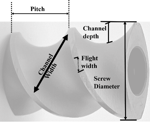
Figure 1. Description of screw terminology
Courtesy: Anton Paar GmbH
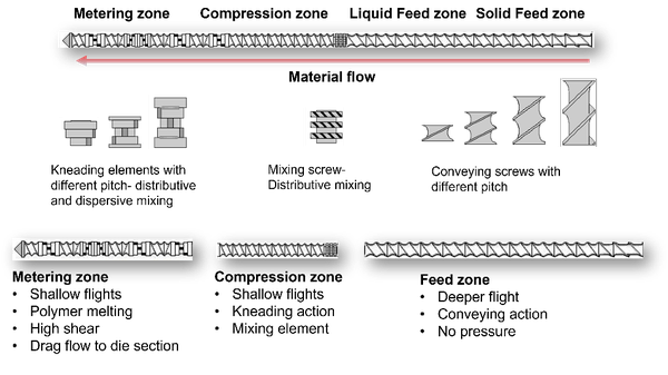
Figure 2. Designing a screw profile for twin screw extrusion processing
Courtesy: Anton Paar GmbH
Screw Elements
Conveying Elements
The deeper flights of these elements enable the efficient conveyance of material to subsequent extruder sections without imparting shear or breaking down ingredients. A deeper channel screw helps better convey material with higher screw volume; screw channel depth decreases in the order; conveying > compression > metering zone
Mixing and Kneading Elements
The kneading elements mainly contribute to the mixing capability of the twin screws. Mixing occurs by shear and elongation during extrusion and performs both distributive and dispersive mixing actions, depending on its geometry. Distributive mixing evenly spreads the dispersed phase without breaking down particles. Dispersive mixing breaks down clumps or agglomerates of material by applying strong shear stress. The wider kneading elements promote dispersive mixing, whereas narrow kneading elements contribute towards distributive mixing (Martin, 2021). The arrangement of kneading elements can also affect the mixing efficiency. Forward kneading elements are less aggressive; neutral kneading elements do not convey the material and thus are aggressive because they only impart energy to the product and increase the residence time. In contrast, the reverse kneading blocks push the material backward, thereby ensuring maximum restriction in the forward flow of material and thus creating maximum shear. Some mixing elements can perform both distributive and dispersive mixing, which improves the shear generation and mixing capabilities (Table 1).
Understanding the Nomenclature of Screw Elements
The nomenclature of the screw elements and their functions are explained based on the elements shown in Table 1.
Conveying Elements
- Gently move material through the extruder without breaking it down.
- SK 40/40 elements move a large bulk of material because they have a larger pitch than SE 30/30 elements.
- SE 20/20 elements compress material and move melted polymers to the end of the extruder because they have a smaller pitch.
- Conveying ability decreases with decreasing pitch.
Reconveying Elements (Reverse Screw Elements)
- Re-conveying elements, also called reverse screw elements, slow down the flow of material.
- SE 10/10 L and SE 20/20 L with reverse pitch direction, slow down the flow of material during extrusion.
- Added before/after the kneading elements to increase shear during extrusion.
Kneading Elements
- Break down material and mix it together.
- KP elements have half-disk widths on both sides.
- KBW elements have full-disk widths on both sides.
- The design of each kneading block affects how it breaks down and mixes material.
- Kneading elements are often placed before and after SE 20/20 elements to move melted material.
- Different designs of each kneading block provide a higher distributive or dispersive shear effect with either positive, negative, or neutral conveying effect depending on the direction of rotation.
- Push material backward to create more shear.
- The length of reverse elements is less than the extruder screw diameter to prevent pressure peaks and significant shear strain in the material.
Toothed Mixing Elements
- Convey forward and mix ingredients evenly.
- Are placed before the extruder compression zone to mix solid and liquid ingredients.
Table 1: Screw Element Designation and Function: Conveying
(The screw element nomenclature differs with extruder manufacturers, the information below is with respect to Brabender extruder screws)
Courtesy: Anton Paar GmbH
| Element type# | Element* | Conveying effect | Pressure build-up in conveying direction | Volume |
|---|---|---|---|---|
| Conveying | SE – 10/20 R | + | ++++ | + |
| SE – 20/20 R | ++ | +++ | + | |
| SE – 30/30 R | +++ | ++ | + | |
| SE – 30/15 R | + | + | + | |
| SK – 40/40 R | ++++ | + | ++ | |
| SK-N- 40/20 R | ++ | + | ++ |
*SE-screw element, SK-thrust edge based on the Erdmenger screw profile, the first number is the flight in pitch, the second is the length of the segment in millimeters, and the letter represents the direction of rotation, R-right ↲
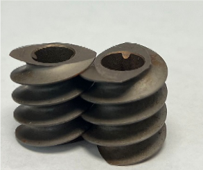
Figure 3. SE – 10/20 R
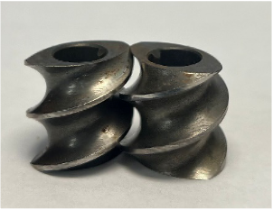
Figure 4. SE – 20/20 R
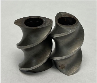
Figure 5. SE – 30/30 R
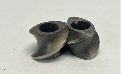
Figure 6. SE – 30/15 R
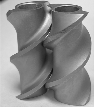
Figure 7. SK – 40/40 R
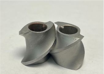
Figure 8. SK-N-40/20 R
Table 1: Screw Element Designation and Function: Re-conveying
| Element type# | Element* | Retaining effect | Pressure build-up in conveying direction | Volume |
|---|---|---|---|---|
| Re-conveying element | SE – 10/10 L | + | +++ | - |
| SE – 20/20 L | ++ | ++ | + |
*SE-screw element, the first number is the flight in pitch, the second is the length of the segment in millimeters, and the letter represents the direction of rotation, L-left ↲
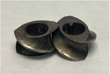
Figure 9. SE – 10/10 L

Figure 10. SE – 20/20 L
Table 1: Screw Element Designation and Function: Kneading Element & Toothed Mixing Element
| Element type# | Element* | Mixing effect (Distributive mixing) | Shear effect (Dispersive mixing) | Conveying effect |
|---|---|---|---|---|
| Kneading element | KP – 45/5/20 R | ++ | + | + |
| KP – 45/5/20 L | +++ | ++ | - | |
| KBW – 45/5/30 R | + | ++ | + | |
| KBW – 45/5/30 L | ++ | +++ | - | |
| Toothed mixing element | Z 8/3/20 | ++ | 0 | + |
*KP-kneading block with half disks on both sides and KBW-kneading blocks with full disk width on both sides, the first number is the angle of displacement of one disk relative to each other, the second number is the number of disks, the third number is the length of the segment, and the letter represents the direction of rotation, R-right, and L-left
*Z-toothed mixing element, the first number is the number of teeth, the second number is the number of tooth rows, and the third number is the length of the element in millimeters ↲
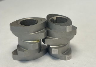
Figure 11. KP – 45/5/20 R
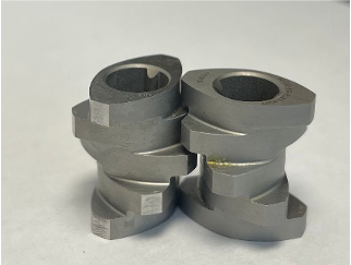
Figure 12. KP – 45/5/20 L
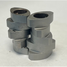
Figure 13. KBW – 45/5/30 R
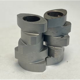
Figure 14. KBW – 45/5/30 L
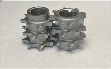
Figure 15. Z 8/3/20
Summary
The design of the extruder screw profile is critical in determining the final product quality. Screws govern the breakdown and transformation of ingredients during processing. Therefore, a thorough knowledge of ingredients properties and functionality is necessary before preparing a screw configuration—especially information on the material's behavior when subjected to heat and shear conditions. For instance, a shear-sensitive material often fails to form a stable product when extruded using a high-shear screw profile. An ideal screw profile will efficiently pump the material, break agglomerates, homogenize and melt the material and develop appropriate melt temperature and pressure at the end of the die. The screw configuration is one aspect of extrusion processing that is untouched and opens the avenue for research and development to develop unique products.
References
Martin, C. 2021. Troubleshooting the ‘Mixing Experience’ in corotating, intermeshing twin-screw extruders. Plastics Technology, 50-54. ↲
Rudolf, E. (1957). U.S. Patent No. 2,814,472. Washington, DC: U.S. Patent and Trademark Office. ↲
Publication date: March 6, 2024
The use of brand names in this publication does not imply endorsement by NC State University or N.C. A&T State University of the products or services named nor discrimination against similar products or services not mentioned.
N.C. Cooperative Extension prohibits discrimination and harassment regardless of age, color, disability, family and marital status, gender identity, national origin, political beliefs, race, religion, sex (including pregnancy), sexual orientation and veteran status.