Irrigation continues to be the most practical and cost effective method of applying wastewater to fields so that the nutrients contained in the wastewater can be used by growing crops. However, irrigation systems have inherent application limitations that make field calibration, irrigation scheduling, and determination of irrigated acreage critical for proper use of the nutrients contained in the applied wastewater.
Irrigation systems are normally designed to satisfy equipment specifications provided in manufacturers’ charts. Information presented in manufacturers’ charts are based on average operating conditions for relatively new equipment. Discharge rates and precipitation rates change over time as equipment ages and components wear. Poor designs and/or improper operation can also cause poor performance. As a result, equipment should be field calibrated regularly to ensure that application rates and uniformity are consistent with values used during the system design and given in manufacturers’ specifications. Field calibration is a simple procedure that involves collecting and measuring the material being applied at several locations. Step-by-step guidelines for field calibration of stationary sprinkler irrigation systems are given in Extension publication AG-553-1, Field Calibration Procedures for Animal Wastewater Application Equipment: Stationary Sprinkler Irrigation System.
Irrigation must be scheduled when fields are dry enough to retain all of the applied liquid within the root zone. If soils are too wet during irrigation, some of the applied wastewater may run off the field or leach below the root zone and become unavailable to the crop. These unused nutrients could contaminate surface or ground water supplies. Determining when and how much wastewater to apply for the prevailing conditions is referred to as irrigation scheduling. Irrigation scheduling techniques and procedures are outlined in Extension publication AG-452-4 Irrigation Scheduling to Improve Water- and Energy-Use Efficiencies.
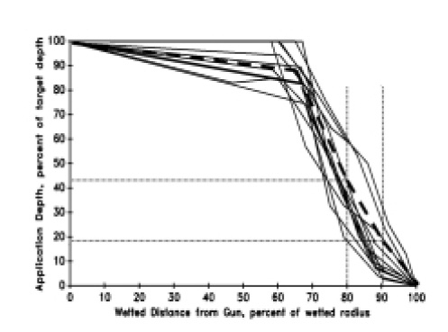
Sprinkler irrigation systems do not uniformly apply water throughout their entire wetted area. Application depths tend to be higher near the sprinkler and decrease gradually within the first 60 to 70 percent of the wetted radius. Beyond this point, the application depth declines quickly to zero at the outer edge. Irrigation design guidelines take equipment limitations into account in establishing recommended overlap ranges to optimize uniformity of coverage. Determining the uniformly irrigated area for stationary sprinklers can be difficult for sprinklers located along the perimeter of the field, for non- uniform sprinkler spacings, or for sprinkler systems with improper overlap. This publication contains step-by-step guidelines for determining irrigated acreage of stationary sprinkler irrigation systems.
Background
Sprinkler spacing and design guidelines have been developed primarily for freshwater irrigation with the primary goal of ensuring that those areas of the field receiving the least amount of water receive an adequate amount to sustain the crop and achieve yield goals. To achieve minimum desired application depths within the “lighter application zones,” sprinkler spacings of 50 to 65 percent of the wetted sprinkler diameter have been determined to be “optimum” to compensate for the declining application along the perimeter. Narrower spacings are typically justified for smaller sprinklers and higher value crops. However, narrower spacings may also result in some zones receiving more water than necessary, and certainly more than the average. A good irrigation design considers these factors and uses a sprinkler spacing that achieves a balance between the relative proportion of “under” and “over” irrigated areas in order to achieve the most uniform application possible.
The application uniformity can be quantified using one of several uniformity indices. The uniformity index recommended for wastewater application is the Christiansen Uniformity Coefficient, Uc. Step-by-step computational procedures are outlined in Extension publication AG-553-1, referenced in the previous section. An application uniformity index of 50 is the minimum acceptable for wastewater application using stationary sprinklers. Irrigation systems should be field calibrated regularly to ensure that application uniformity is within the acceptable range. Field calibration can also be used to determine the area within a field receiving an acceptable uniform application.
Irrigated Acreage
In an effort to answer technical specialists’ questions and to provide uniform interpretations of the state’s animal waste management rules, the North Carolina General Assembly formed an interagency committee in 1996. The SB 1217 Interagency Committee is composed of two representatives of each of the five agencies with responsibilities for the development and/or enforcement of animal waste management rules. The committee recently adopted guidelines and procedures for determining the irrigated acreage that can count toward the acreage needed to satisfy the land application requirements in the Certified Animal Waste Management Plan (CAWMP). The committee considered many factors including recommendations from irrigation engineers, certified irrigation designers, and industry representatives before arriving at these guidelines. The irrigated acreage determined by these procedures is intended to “reasonably and practically” account for physical limitations of the application equipment. The “irrigated acreage” computed by the procedures presented below must equal or exceed the acreage requirement specified in the CAWMP for proper nutrient use.
The irrigated area determination includes two broad categories: existing irrigation systems– those systems installed before the guidelines were finalized–and new or expanded irrigation systems installed after the SB 1217 committee released the third revision of the Sixth Guidance Document. Future updates and revisions may occur, so you should refer to the most recent Guidance Document for the latest interpretation and effective dates.
For the purpose of computing the irrigated acreage available to satisfy the CAWMP, the SB 1217 Interagency Committee adopted the term “CAWMP wettable acre” to be applied to existing systems. The irrigated acreage for new or expanded systems should be based on standard irrigation design guidelines, which are based on the effective design area. The term expanded irrigation system applies to new irrigation components that wet an area of a field that was not wetted before adoption of the new guidelines. These terms are defined below.
Existing irrigation systems–For stationary sprinkler systems designed and installed in accordance with standard overlap recommendations (sprinkler spacing between 50 and 70 percent of verified wetted diameter) and laid out with multiple overlapping laterals, the irrigated area allowance is the entire “net wetted area” in the field. The net wetted area is the part of the field that gets “wetted” by one or more sprinklers when operated during normal conditions, i.e., wind speed under 5 mph.
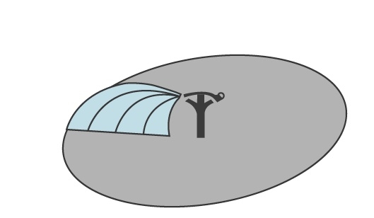
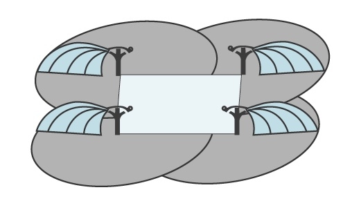
The “wetted area” for a single sprinkler operated without overlap is the area inscribed within its wetted diameter as shown in Figure 1. For multiple sprinklers such as shown in Figure 2, the entire shaded area gets wetted; however, in this case, the wetted area is referred to as “net wetted area.” Due to overlap, some areas are wetted by multiple sprinklers. Obviously these overlap areas cannot be counted twice, hence the term “net” is used. The sprinkler spacing is represented by the inscribed rectangle. For a stationary sprinkler system, there are two sprinkler designations within the field that affect determination of irrigated acreage.
- Interior sprinklers
- Exterior sprinklers
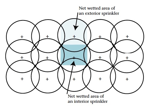
An interior sprinkler is any sprinkler that receives overlap on all sides. For a rectangular spacing within the recommended spacing range (less than 70 percent of wetted diameter), an interior sprinkler receives overlap from eight adjacent sprinklers as shown in Figure 3, although only four sprinklers contribute significant overlap. An interior sprinkler is a sprinkler that receives overlap from the four adjacent sprinklers along perpendicular transects drawn through the sprinkler in question. For the sprinkler pattern shown in Figure 3, only the three center sprinklers are interior sprinklers, and the net wetted area for one interior sprinkler is represented by the center shaded rectangle. The other 12 sprinklers are exterior, and the net wetted area of one exterior sprinkler is represented by the top shaded area. Note that the two shaded areas are not the same size.
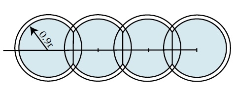
For stationary sprinkler systems arranged in a single lateral pattern, the net wetted area should be computed based on 90 percent of the wetted diameter as shown in Figure 4. The outer portion that does not overlap with an adjacent sprinkler is not included for reasons explained in the next section. For any system in which the lateral spacing exceeds 70 percent of the wetted diameter, each lateral should be treated as a “single lateral” case. If sprinkler spacing along the lateral also exceeds 70 percent of wetted diameter, each sprinkler should be treated as a single sprinkler case.
The system layout, including determination of lateral and sprinkler spacing, lateral configuration, and number of interior and exterior sprinklers, must be determined in order to compute the CAWMP wettable acres.
New or Expanded Irrigation Systems–
New or expanded irrigation systems should follow recommended design standards, which base the allowable irrigated area on the effectively irrigated area, referred to as the “design area.”
The effective irrigated area is the wetted area that receives at least 50 percent of the target application amount. Recent field calibration measurements have determined this to be the area that falls within 78 percent of the wetted radius as shown in Figure 5. Note that application depths remain within 90 percent of the target amount out to 60 percent of the wetted radius. Between 60 and 70 percent of the wetted radius, application amounts still remain within 80 percent of the target application amount. But beyond 70 percent of the wetted radius, application amounts drop off quickly, declining to 50 percent by 78 percent of the wetted radius. Beyond 90 percent of the wetted radius, the application depth drops below 20 percent.
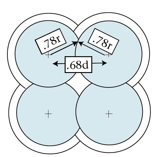
Traditional design spacing guidelines established by North Carolina Cooperative Extension or stationary sprinklers have been 50 to 65 percent of manufacturers’ published wetted diameter. When sprinklers are arranged in a square pattern, the point of intersection of the 50 percent application amount (78 percent of wetted radius as shown in Figure 5) occurs at a sprinkler spacing of 68 percent of the wetted diameter. This is shown graphically in Figure 6. At wider spacings, there is inadequate overlap resulting in “dry zones.” The relative proportion of dry zone (unshaded area in the center of Figure 6) increases as the spacing increases. A conservative rule of thumb for sprinkler spacing has been not to exceed 65 percent of the manufacturer’s published wetted diameter. Recent measurements on more than 50 systems determined that field-measured wetted diameters averaged 10 percent less than values published by manufacturers. A spacing based on 70 percent of field-measured diameter is roughly the same as a spacing based on 65 percent of manufacturers’ values. The data presented in Figure 5 confirm irrigation design specifications previously recommended by North Carolina Cooperative Extension and should continue to be applied to new or expanded systems. Spacings greater than 70 percent of the verified wetted diameter or 65 percent of the wetted diameter published in manufacturers’ literature are considered excessive and result in unacceptable uniformity.
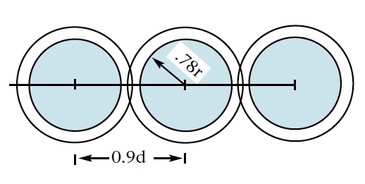
The irrigated area allowance of a single or excessively spaced sprinkler is the area inscribed within 78 percent of the wetted radius as shown in Figure 7. This is regardless of when the system was installed. You should treat a stand-alone sprinkler or any sprinklers located on laterals in which the lateral spacing and the sprinkler spacing along the lateral exceed 70 percent as a single sprinkler. For example, in Figure 7, the spacing along the lateral is 90 percent of the wetted diameter, so the area of each sprinkler is computed as a single sprinkler rather than as a single lateral as was shown in Figure 4. In Figure 4, the shaded areas overlap, therefore computations are based on a “single lateral.” In Figure 7, the shaded areas do not overlap, therefore the computations are based on each sprinkler individually.
Field Measurements
To accurately calculate the irrigated area, determine the wetted diameter or radius of the sprinkler system. There are two methods for determining the wetted diameter, and both require operating the system:
- Directly measure the wetted diameter (footprint), which is the preferred method
- Estimate wetted diameter from field-measured sprinkler pressure and values published in manufacturers’ charts for the observed pressure.
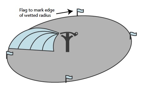
Footprint measurement–Footprint measurement involves observing, marking, and measuring the farthest distances from the sprinkler that get wetted. Field data should be collected on at least two sprinklers located on two different lateral lines farthest from the pump. In both cases, the sprinklers should be located at least 1/4 of the way down the lateral line. Measurements should be made during very light wind (less than 5 mph). The wetted distance from each sprinkler should be determined at four points along the perimeter as indicated in Figure 8. The system should be operated long enough for all air to be purged from the system before starting to make measurements. With the system operating at normal pressure:
- Standing just outside the wetted perimeter, observe and flag the farthest point getting wetted for each of three consecutive passes of the sprinkler.
- Select one flag to mark the average distance of the three observations. Remove the other two flags.
- Move 90 degrees around the wetted perimeter and repeat steps 1 and 2. Continue until the wetted perimeter has been flagged on four sides of the sprinkler as shown in Figure 8.
- Move to sprinkler #2 and repeat steps 1 through 3.
- Measure and record the distances from the sprinkler to each flag.
- Determine the average of the four measurements for each sprinkler.
- Compare the two sprinklers, and if the measure- ments are within 10 percent, compute the average of the two and this will be the wetted radius. If the difference between the measurements is more than 10 percent, repeat steps 1 through 6 for a third sprinkler.
- Compare the measurements for all three sprinklers and identify the two that are closest. If their difference is less than 10 percent, compute the average of the two, and this value is the wetted radius. If the difference is more than 10 percent, repeat steps 1 through 6 until you identify two sprinklers that fall within 10 percent of each other.
Pressure measurement–The wetted diameter can also be estimated from pressure measurements if the pressure is measured at the sprinkler. Pump pressure is NOT an acceptable substitute.
Collect field data for at least two sprinklers located on two different lateral lines farthest from the pump. In both cases, the sprinklers should be located at least 1/4 of the way down the lateral line. The system should be operated long enough for all air to be purged from the system before measuring the pressure.
If you are using portable quick-connect risers, it is suggested that you configure one riser with a pressure gauge so that you can easily move the entire assembly to several laterals. This riser-pressure gauge assembly should be an “extra” riser and used only when pressure measurements are needed. If it is used routinely, the gauge will soon foul and give erroneous measurements.
For permanent risers, you should install a tee with a threaded reducing port in two riser pipes. You should temporarily install a pressure gauge in the threaded port to make pressure measurements. Once the measurement has been made, it is recommended that you remove the gauge and plug the port. The same gauge can be used at all locations. An alternative approach is to install a shut-off valve between the riser pipe and pressure gauge and leave the gauge permanently mounted.
It is also necessary to determine the exact size of the nozzle opening. Most manufacturers stamp the nozzle size on the end of the nozzle. If this is not readable, a drill index can be used to determine the size of small nozzles (less than 1/2-inch diameter). Simply insert the shank end of a drill bit into the nozzle opening until a bit providing a snug fit is found. Read and record the size of the drill bit.
Once you have measured the operating pressure and nozzle opening, you can estimate the wetted diameter from manufacturers’ literature. When using Tables 1 through 5 to determine irrigated acreage, reduce the value taken from manufacturers’ charts by 10 percent.
Determining Irrigated Acreage
Once you have collected the necessary field data and determined the wetted radius or diameter, you can compute the CAWMP wettable acres.
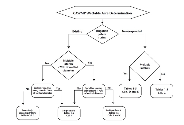
Computations are not difficult; but they can become cumbersome for non-uniform sprinkler spacings, sprinkler systems with improper overlap, and sprinklers located along the perimeter of the field. To simplify the determination of irrigated acreage, computations have been tabulated in Tables 1 through 5 for typical spacings and patterns. Use of these tables requires precise determination of wetted diameter, system layout, and the number of interior and exterior sprinklers as defined earlier. A flowchart for using the tables is shown in Figure 12.
Irrigated acreage based on net wetted area for existing systems is shown in columns (B), (C), and (F) in Tables 1 through 5. Irrigated acreage based on design area for new or expanded systems is shown in columns (D), (E), and (G). You should follow these general guidelines in using these tabulated values. Decisions are to be made on a field-by-field basis as referenced in the CAWMP.
- Determine the number of interior and exterior sprinklers for each field.
- Determine whether the system in each field satisfies the existing or new designation.
- From the Field Data Worksheet, determine the lateral spacing and sprinkler spacing along the lateral.
-
Determine whether the system satisfies the multiple lateral or single lateral pattern. If the lateral spacing exceeds 70 percent of the wetted diameter but the sprinkler spacing along the lateral is less than 70 percent, you should treat the systems as a single lateral system and base the irrigated acreage read from column F (from the appropriate table) on sprinkler spacing along the lateral.
If both the lateral and sprinkler spacing exceeds 70 percent, the irrigated area should be read from Table 6.
-
Read the irrigated area per sprinkler for the given wetted diameter from the appropriate column based on pattern, spacing, and sprinkler type.
If the lateral or sprinkler spacing falls between the tabulated values, interpolate or round down and use the table for the next lowest value shown. For example, if the computed spacing is between 60 and 64 percent, use the 60 percent table (Table 3).
If the pattern is rectangular (rather than square as shown), for example, lateral spacing is 65 percent but sprinkler spacing along lateral is 55 percent, average these two values and use the appropriate table. In this case, use Table 3, 60 percent table. As before, if the averaged value falls between the tabulated values, interpolate between the appropriate tables or round down to the next lowest tabulated value.
- Multiply the tabulated irrigated acreage value per sprinkler by the number of sprinklers in each category. Add all of these, and the sum is the total irrigated acreage for the field.
A flowchart summarizing the decision processes for using Tables 1 through 6 is shown in Figure 12.
Determining Irrigated Acreage
EXAMPLES
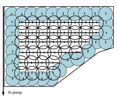
Case I: Multiple laterals with uniform spacing. Figure 9 shows a typical lateral and sprinkler pattern for a stationary sprinkler system. This existing system
has eight laterals of varying length laid out in the field.
- Determine the number of interior and exterior sprinklers for each field (Field Data Worksheet item 7). Referring to Figure 9, count all sprinklers along the perimeter of the field to determine the number of exterior sprinklers. Any sprinkler not receiving overlap on four sides should be counted as an exterior sprinkler.
Number of exterior sprinklers = 30
Number of interior sprinklers = 42
- Determine whether the system in each field satisfies the existing or new designation.
System satisfies existing designation.
- From the field data, determine the lateral and sprinkler spacing along the lateral and wetted diameter.
The appropriate Field Data Worksheet shows the lateral spacing (Field Data Worksheet item 3) is 80 feet and the sprinkler spacing (Field Data Worksheet item 3) along the lateral is 80 feet. The wetted diameter (Field Data Worksheet item 5) is 127 feet.
Sprinkler spacing as a percentage of wetted diameter is: 80 feet / 127 feet = 63 percent
- Determine whether the system satisfies the multiple lateral or single lateral definition.
System satisfies multiple lateral system definition with lateral spacing equal to 63 percent of wetted diameter.
- Read the irrigated area per sprinkler for the given wetted diameter from the appropriate column based on pattern, spacing, and sprinkler type.
To use the tables without interpolating, round down the wetted diameter to 125 feet and the lateral spacing to 60 percent of wetted diameter.
Using Table 3, for wetted diameter equal to 125 feet, existing system with multiple laterals, 60 percent lateral spacing, read
area of interior sprinkler from Column (B) =
0.129 acres
area of exterior sprinkler from Column (C) =
0.165 acres
-
Multiply the tabulated irrigated acreage value per sprinkler by the number of sprinklers in each category (column B, C, or F for an existing system; column D, E, or G for a new or expanded system). Add these. The sum is the total irrigated acreage for the field.
30 exterior sprinklers X 0.165 acres = 4.95 acres
42 interior sprinklers X 0.129 acres = 5.42 acres
Total irrigated area of field
4.95 ac + 5.42 ac = 10.37 acres
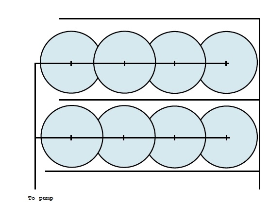
Case II: Single laterals with uniform sprinkler spacing along lateral. Figure 10 shows a typical lateral and sprinkler pattern for a stationary sprinkler system in narrow fields. Data and irrigated area must be reported on a field-by-field basis. In this example, fields are surrounded by drainage ditches spaced 330 feet apart. This existing system has one lateral per field with model 100 guns.
- Determine the number of interior and exterior sprinklers for each field (Field Data Worksheet item 7). Referring to Figure 10, treat each lateral as a single lateral; therefore, you do not have to distinguish between interior and exterior sprinklers. Number of sprinklers per lateral = 4
-
Determine whether the system in each field satisfies the existing or new designation.
System satisfies existing designation.
-
From the field data, determine the lateral and sprinkler spacing along the lateral and wetted diameter.
The Field Data Worksheet (item 3) shows the sprinkler spacing along the lateral is 180 feet. The wetted diameter (item 5) is 275 feet.
Sprinkler spacing as a percentage of wetted diameter is: 180 feet / 275 feet = 65.5 percent.
-
Determine whether the system satisfies the multiple lateral or single lateral definition.
System satisfies single lateral system definition with sprinkler spacing along laterals equal to 65.5 percent of wetted diameter.
-
Read the irrigated area per sprinkler for the given wetted diameter from the appropriate column based on pattern, spacing, and sprinkler type.
To use the tables without interpolating, round down wetted diameter to 270 feet and sprinkler spacing to 65 percent of wetted diameter.
Using Table 4, wetted diameter equal to 270 feet, existing system with single laterals, 65 percent sprinkler spacing, read area of sprinkler from Column (F)
0.886 acres.
-
Multiply the tabulated irrigated acreage value per sprinkler by the number of sprinklers per lateral. This gives the CAWMP Irrigated Acreage for the field.
4 sprinklers X 0.886 acres = 3.54 acres per field
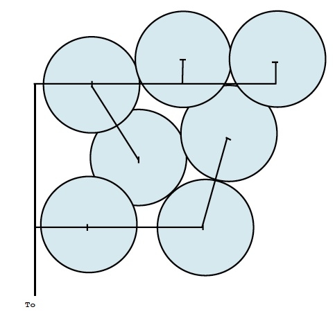
Case III: Non-uniform sprinkler spacing along lateral. Figure 11 shows an irregular sprinkler pattern sometimes fitted to an odd-shaped field. This existing system has seven irregularly spaced model 100 guns.
-
Determine the number of interior and exterior sprinklers for each field (Field Data Worksheet item 7). Referring to Figure 11, treat all sprinklers the same.
Number of sprinklers per field = 7
-
Determine whether the system in each field satisfies the existing or new designation.
System satisfies existing designation.
-
From the field data, determine the lateral and sprinkler spacing along the lateral and wetted diameter.
The Field Data Worksheet (item 3) shows the sprinkler spacing along the laterals ranges from 200 to 240 feet. The wetted diameter (item 5) is 275 feet.
Sprinkler spacing as a percentage of wetted diameter varies from:
200 feet / 275 feet = 72.7 percent
240 feet / 275 feet = 87.3 percent
-
Determine whether the system satisfies the multiple lateral or single lateral definition.
With irregular lateral and sprinkler spacings varying from 72 to 87 percent of wetted diameter, the system satisfies neither multiple nor single lateral criteria. Therefore, treat it as an excessively spaced sprinkler system.
-
Read the irrigated area per sprinkler for the given wetted diameter from the appropriate column based on pattern and spacing.
Using Table 6, for wetted diameter equal to 275 feet, existing system with sprinkler spacing greater than 70 percent, read area of sprinkler from Column G
0.80 for wetted dia. = 270 feet
0.86 for wetted dia. = 280 feet Interpolating, area = 0.83 ac for wetted dia. = 275 feet
-
Multiply the tabulated irrigated acreage value per sprinkler by the number of sprinklers. Add these. The sum is the total irrigated acreage for the field.
7 sprinklers X 0.83 acres = 5.81 acres per field
Summary
Animal waste management operations that rely on spray irrigation systems may be required to have a wettable acre determination completed to ensure nutrients contained in the wastewater are applied to adequate land at agronomic rates. All CAWMP will be reviewed by state Division of Water Quality or Division of Soil and Water field inspectors to determine whether a wettable acre determination is indeed required. If so, the Field Data Worksheets and Computational Worksheet that follow will have to be completed for stationary sprinkler or stationary gun systems and added to the CAWMP. A wettable acre (WA) designated technical specialist must complete and sign the Computational Worksheet to certify that the irrigation system can be operated so that the wastewater nutrients are applied to appropriate areas. Step-by-step procedures for completing the CAWMP wettable acres determination have been developed, along with tables from which irrigated acreage can be determined for various irrigation system designs.
CAWMP Wettable Acre Terms
CAWMP wettable acre–the irrigated acreage that the SB 1217 Interagency Committee allows to be counted toward the land application area requirement of the Certified Animal Waste Management Plan for existing irrigation systems.
Effective design area–the portion of the wetted area that receives at least 50 percent of the target application amount (applies to new or expanded irrigation systems).
Excessively spaced sprinkler–sprinkler spacing along a lateral that exceeds 70 percent of the verified wetted diameter or 65 percent of the wetted diameter value published in manufacturers’ literature.
Existing irrigation system–an irrigation system that was installed before release of the third revision of the Sixth Guidance Document.
Multiple lateral irrigation system–an irrigation system with two or more laterals equally spaced between 50 and 70 percent of the verified wetted diameter.
Net wetted area–the part of the field that gets wetted by two or more sprinklers operated with partially overlapping radii (applies to existing irrigation systems).
New or expanded irrigation system–any component of an irrigation system that wets a portion of a field that was not wetted before the CAWMP wettable acre rules were finalized.
Single lateral irrigation system–an irrigation system with only one lateral per field, or laterals spaced farther apart than 70 percent of the verified wetted diameter.
Verified wetted diameter–field-measured distance from one side of a wetted perimeter to the opposite side of the wetted perimeter.
Wetted area–the area that becomes wetted as a sprinkler rotates. It is the area within the circle inscribed by the wetted radius.
Wetted diameter–the diagonal distance from one side of a wetted perimeter through the point of sprinkler rotation to the opposite side of the wetted perimeter. Wetted diameter is twice the wetted radius.
Wetted radius–the distance from a sprinkler to a point along the edge of the wetted perimeter. Wetted radius is the distance the sprinkler throws water.
Stationary Sprinkler System Field Data Worksheet
*Locate each sprinkler or sprinkler location on the map. Indicate whether it is full circle or part circle. Show the location of the supply line. Irrigated acres are determined by lateral line, by zone, or by field.
- Sprinkler make and model number______________________________________________________________________
- Sprinkler nozzle size______________________________________________________________________[inch]
- Lateral spacing _______________________________[feet] by sprinkler spacing along lateral _______________________________________[feet]
- Operating pressure at the sprinkler __________________________________[psi]
- Sprinkler wetted diameter _____________________[feet]. ________measured or ________determined from chart.
- Number of sprinklers operating at one time_____________________
- Total number of sprinklers or sprinkler locations in the system
Exterior sprinklers: _____________________full circle _____________________part circle
Interior sprinklers: _____________________full circle
Sprinkler locations permanently marked: _____________________yes _____________________no
-
Supply line _____________________Permanent pipe_____________________Portable pipe_____________________
-
Lateral line size _____________________[inch]. If there is more than one size, indicate the size and approximate length of each. Can be done on the map.**
-
Lateral line length _____________________[feet]. (Longest lateral)**
-
Supply line size_____________________ [inch]. If there is more than one size, indicate the size and approximate length of each. Can be done on the map.**
-
Supply line length _____________________[feet]. Maximum pumping distance.**
-
Pump make and model number_____________________**
-
Pump capacity _____________________[gpm]**
-
Engine make and model number_____________________, or**
-
Electric motor horsepower and rpm _____________________[hp] _____________________[rpm]**
Note: It is strongly recommended that you field measure the sprinkler wetted diameter. You should do this on the longest lateral about half-way down the lateral.
** Optional data, furnish where possible ↲
***Information furnished by:
Signature of owner or facility representative_______________________________________________________________
Printed name of owner or facility representative_______________________________________________________________
Date________________________
Signature of technical specialist_______________________________________________________________
Printed name of technical specialist_______________________________________________________________
Date________________________
*** Only the person or people collecting the data should sign the Field Data Worksheet. ↲
Stationary Gun System Field Data Worksheet *
*Locate each gun or gun location on the map. Indicate whether it is full circle or part circle. Show the location of the supply line. Irrigated acres are determined by lateral line, by zone, or by field.
- Gun make and model number ___________________________________________________________________________
- Gun nozzle size _________________ [inch], ________________ ring orifice, ___________________ taper bore orifice
- Lateral spacing ___________________________ [feet] by gun spacing along lateral ________________________ [feet]
- Operating pressure at the gun _______________________________________________________________________ [psi]
- Gun wetted diameter _______________ [feet]. ____________ measured or __________ determined from gun chart
- Number of guns operating at one time ___________________________________________________________________
-
Total number of guns or gun locations in the system ______________________________________________________
Exterior guns: ______________________________ full circle _________________________________ part circle
Interior guns: _________________________________________________________________________ full circle
Gun locations permanently marked: _____________________________ yes _________________________ no
-
Supply line __________________________________ Permanent pipe _____________________________ Portable pipe
-
Lateral line size __________ [inch]. If there is more than one size, indicate the size and approximate length of each. Can be done on the map.**
-
Lateral line length ________________________________________________________________ [feet]. (Longest lateral)**
-
Supply line size __________ [inch]. If there is more than one size, indicate the size and approximate length of each. Can be done on the map.**
-
Supply line length ___________________________________________________ [feet]. Maximum pumping distance.**
-
Pump make and model number _________________________________________________________________________**
-
Pump capacity ___________________________________________________________________________________ [gpm]**
-
Engine make and model number _____________________________________________________________________, or**
-
Electric motor horsepower and rpm ________________________________ [hp] __________________________ [rpm]**
Note: It is strongly recommended that you field measure the gun wetted diameter. It should be done on the longest lateral about half-way down the lateral.
**Optional data, furnish where possible ↲
*** Information furnished by
Signature of owner or facility representative__________________________________
Printed name of owner or facility representative__________________________________
Date______________________________
Signature of technical specialist_________________________________
Printed name of technical specialist________________________________
Date_____________________________
*** Only the person or people collecting the data should sign the Field Data Worksheet. ↲
Stationary Sprinkler /Gun System Wettable Acre Computational Worksheet
- Farm number (identification) _______________ Field number (identification) _______________
- Irrigation system designation
___________Existing irrigation system
___________ New/expanded irrigation system
- Number of stationary sprinklers ___________ # Interior sprinklers __________ # Exterior sprinklers
- Wetted diameter ___________ [feet] from Field Data Worksheet
-
Spacing
___________ Sprinkler spacing along lateral [feet]
___________ Sprinkler spacing as a percentage of wetted diameter
-
Sprinkler pattern
___________ Multiple laterals
___________ Single lateral
___________ Excessively spaced sprinklers
-
Read the irrigated area per sprinkler for the given wetted diameter from the appropriate table and column based on pattern, spacing, and sprinkler location.
______ Acres per interior sprinkler from Table _____ Column _____
______ Acres per exterior sprinkler from Table _____ Column _____
-
Multiply the tabulated irrigated acreage value per sprinkler by the number of sprinklers of each category in the field. Add all of these. The sum is the total irrigated acreage for the field.
______ (a) Acres per interior sprinkler × _______ # Sprinklers = _________ Acres
______ (b) Acres per exterior sprinkler × _______ # Sprinklers = _________ Acres
______ Total wettable acres for field (Sum: 8a + 8b)
Wettable Acre Computational Worksheet completed by:
___________________________________ Date:________________
Signature of technical specialist
Table 1
|
wetted diameter (feet) |
Existing System with proper overlap and multiple laterals |
New or Expanded System with multiple laterals |
Existing single lateral |
New/Expanded single lateral |
||
|
net wetted area of an interior sprinkler (acres) |
net wetted area of an exterior sprinkler (acres) |
design area of an interior sprinkler (acres) |
design area of an exterior sprinkler (acres) |
net wetted area of each sprinkler (acres) |
design area of each sprinkler (acres) |
|
|
(A) |
(B) |
(C) |
(D) |
(E) |
(F) |
(G) |
|
80 |
0.037 |
0.053 |
0.037 |
0.045 |
0.063 |
0.053 |
|
85 |
0.041 |
0.060 |
0.041 |
0.051 |
0.071 |
0.060 |
|
90 |
0.046 |
0.068 |
0.046 |
0.057 |
0.079 |
0.067 |
|
95 |
0.052 |
0.075 |
0.052 |
0.063 |
0.088 |
0.075 |
|
100 |
0.057 |
0.084 |
0.057 |
0.070 |
0.098 |
0.083 |
|
105 |
0.063 |
0.092 |
0.063 |
0.077 |
0.108 |
0.091 |
|
110 |
0.069 |
0.101 |
0.069 |
0.085 |
0.118 |
0.100 |
|
115 |
0.076 |
0.111 |
0.076 |
0.093 |
0.129 |
0.110 |
|
120 |
0.083 |
0.120 |
0.083 |
0.101 |
0.141 |
0.119 |
|
125 |
0.090 |
0.131 |
0.090 |
0.110 |
0.153 |
0.130 |
|
130 |
0.097 |
0.141 |
0.097 |
0.119 |
0.165 |
0.140 |
|
135 |
0.105 |
0.152 |
0.105 |
0.128 |
0.178 |
0.151 |
|
140 |
0.112 |
0.164 |
0.112 |
0.138 |
0.192 |
0.163 |
|
145 |
0.121 |
0.176 |
0.121 |
0.148 |
0.206 |
0.174 |
|
150 |
0.129 |
0.188 |
0.129 |
0.158 |
0.220 |
0.187 |
|
155 |
0.138 |
0.201 |
0.138 |
0.169 |
0.235 |
0.199 |
|
160 |
0.147 |
0.214 |
0.147 |
0.180 |
0.250 |
0.212 |
|
165 |
0.156 |
0.228 |
0.156 |
0.191 |
0.266 |
0.226 |
|
170 |
0.166 |
0.242 |
0.166 |
0.203 |
0.283 |
0.240 |
|
175 |
0.176 |
0.256 |
0.176 |
0.215 |
0.299 |
0.254 |
|
180 |
0.186 |
0.271 |
0.186 |
0.227 |
0.317 |
0.269 |
|
185 |
0.196 |
0.286 |
0.196 |
0.240 |
0.335 |
0.284 |
|
190 |
0.207 |
0.302 |
0.207 |
0.253 |
0.353 |
0.300 |
|
195 |
0.218 |
0.318 |
0.218 |
0.267 |
0.372 |
0.316 |
|
200 |
0.230 |
0.334 |
0.230 |
0.281 |
0.391 |
0.332 |
|
210 |
0.253 |
0.369 |
0.253 |
0.310 |
0.431 |
0.366 |
|
220 |
0.278 |
0.404 |
0.278 |
0.340 |
0.473 |
0.402 |
|
230 |
0.304 |
0.442 |
0.304 |
0.371 |
0.517 |
0.439 |
|
240 |
0.331 |
0.481 |
0.331 |
0.404 |
0.563 |
0.478 |
|
250 |
0.359 |
0.522 |
0.359 |
0.439 |
0.611 |
0.519 |
|
260 |
0.388 |
0.565 |
0.388 |
0.474 |
0.661 |
0.561 |
|
270 |
0.418 |
0.609 |
0.418 |
0.512 |
0.713 |
0.605 |
|
280 |
0.450 |
0.655 |
0.450 |
0.550 |
0.766 |
0.651 |
|
290 |
0.483 |
0.703 |
0.483 |
0.590 |
0.822 |
0.698 |
|
300 |
0.517 |
0.752 |
0.517 |
0.632 |
0.880 |
0.747 |
|
310 |
0.552 |
0.803 |
0.552 |
0.674 |
0.939 |
0.797 |
|
320 |
0.588 |
0.856 |
0.588 |
0.719 |
1.001 |
0.850 |
|
330 |
0.625 |
0.910 |
0.625 |
0.764 |
1.065 |
0.904 |
|
340 |
0.663 |
0.966 |
0.663 |
0.811 |
1.130 |
0.959 |
|
350 |
0.703 |
1.024 |
0.703 |
0.860 |
1.198 |
1.017 |
|
360 |
0.744 |
1.083 |
0.744 |
0.910 |
1.267 |
1.075 |
|
370 |
0.786 |
1.144 |
0.786 |
0.961 |
1.338 |
1.136 |
|
380 |
0.829 |
1.207 |
0.829 |
1.014 |
1.412 |
1.198 |
|
390 |
0.873 |
1.271 |
0.873 |
1.068 |
1.487 |
1.262 |
|
400 |
0.918 |
1.337 |
0.918 |
1.123 |
1.564 |
1.328 |
|
410 |
0.965 |
1.405 |
0.965 |
1.180 |
1.643 |
1.395 |
|
420 |
1.012 |
1.474 |
1.012 |
1.238 |
1.724 |
1.464 |
|
430 |
1.061 |
1.545 |
1.061 |
1.298 |
1.808 |
1.534 |
|
440 |
1.111 |
1.618 |
1.111 |
1.359 |
1.893 |
1.607 |
|
450 |
1.162 |
1.692 |
1.162 |
1.421 |
1.980 |
1.680 |
Table 2
|
Table 2. Irrigated Area Allowances for Stationary Sprinkler Systems with Square Spacing (Lateral and sprinkler spacing based on 55 percent of wetted diameter) |
|||||||
|
wetted diameter (feet) |
Existing System with proper overlap and multiple laterals |
New or Expanded System with multiple laterals |
Existing single lateral |
New/Expanded single lateral |
|
||
|
net wetted area of an interior sprinkler (acres) |
net wetted area of an exterior sprinkler (acres) |
design area of an interior sprinkler (acres) |
design area of an exterior sprinkler (acres) |
net wetted area of each sprinkler (acres) |
design area of each sprinkler (acres) |
|
|
|
(A) |
(B) |
(C) |
(D) |
(E) |
(F) |
(G) |
|
|
80 |
0.044 |
0.061 |
0.044 |
0.051 |
0.068 |
0.057 |
|
|
85 |
0.050 |
0.068 |
0.050 |
0.057 |
0.077 |
0.065 |
|
|
90 |
0.056 |
0.077 |
0.056 |
0.064 |
0.086 |
0.073 |
|
|
95 |
0.063 |
0.085 |
0.063 |
0.072 |
0.096 |
0.081 |
|
|
100 |
0.069 |
0.095 |
0.069 |
0.080 |
0.106 |
0.090 |
|
|
105 |
0.077 |
0.104 |
0.077 |
0.088 |
0.117 |
0.099 |
|
|
110 |
0.084 |
0.114 |
0.084 |
0.096 |
0.128 |
0.108 |
|
|
115 |
0.092 |
0.125 |
0.092 |
0.105 |
0.140 |
0.118 |
|
|
120 |
0.100 |
0.136 |
0.100 |
0.115 |
0.153 |
0.129 |
|
|
125 |
0.109 |
0.148 |
0.109 |
0.124 |
0.166 |
0.140 |
|
|
130 |
0.117 |
0.160 |
0.117 |
0.134 |
0.179 |
0.151 |
|
|
135 |
0.127 |
0.172 |
0.127 |
0.145 |
0.193 |
0.163 |
|
|
140 |
0.136 |
0.185 |
0.136 |
0.156 |
0.208 |
0.176 |
|
|
145 |
0.146 |
0.199 |
0.146 |
0.167 |
0.223 |
0.188 |
|
|
150 |
0.156 |
0.213 |
0.156 |
0.179 |
0.239 |
0.202 |
|
|
155 |
0.167 |
0.227 |
0.167 |
0.191 |
0.255 |
0.215 |
|
|
160 |
0.178 |
0.242 |
0.178 |
0.204 |
0.272 |
0.229 |
|
|
165 |
0.189 |
0.257 |
0.189 |
0.216 |
0.289 |
0.244 |
|
|
170 |
0.201 |
0.273 |
0.201 |
0.230 |
0.307 |
0.259 |
|
|
175 |
0.213 |
0.290 |
0.213 |
0.244 |
0.325 |
0.274 |
|
|
180 |
0.225 |
0.306 |
0.225 |
0.258 |
0.344 |
0.290 |
|
|
185 |
0.238 |
0.324 |
0.238 |
0.272 |
0.363 |
0.307 |
|
|
190 |
0.251 |
0.341 |
0.251 |
0.287 |
0.383 |
0.323 |
|
|
195 |
0.264 |
0.359 |
0.264 |
0.302 |
0.404 |
0.341 |
|
|
200 |
0.278 |
0.378 |
0.278 |
0.318 |
0.425 |
0.358 |
|
|
210 |
0.306 |
0.417 |
0.306 |
0.351 |
0.468 |
0.395 |
|
|
220 |
0.336 |
0.458 |
0.336 |
0.385 |
0.514 |
0.434 |
|
|
230 |
0.367 |
0.500 |
0.367 |
0.421 |
0.562 |
0.474 |
|
|
240 |
0.400 |
0.545 |
0.400 |
0.458 |
0.611 |
0.516 |
|
|
250 |
0.434 |
0.591 |
0.434 |
0.497 |
0.663 |
0.560 |
|
|
260 |
0.469 |
0.639 |
0.469 |
0.538 |
0.718 |
0.606 |
|
|
270 |
0.506 |
0.689 |
0.506 |
0.580 |
0.774 |
0.653 |
|
|
280 |
0.544 |
0.741 |
0.544 |
0.623 |
0.832 |
0.702 |
|
|
290 |
0.584 |
0.795 |
0.584 |
0.669 |
0.893 |
0.754 |
|
|
300 |
0.625 |
0.851 |
0.625 |
0.716 |
0.955 |
0.806 |
|
|
310 |
0.667 |
0.908 |
0.667 |
0.764 |
1.020 |
0.861 |
|
|
320 |
0.711 |
0.968 |
0.711 |
0.814 |
1.087 |
0.917 |
|
|
330 |
0.756 |
1.029 |
0.756 |
0.866 |
1.156 |
0.976 |
|
|
340 |
0.803 |
1.093 |
0.803 |
0.919 |
1.227 |
1.036 |
|
|
350 |
0.851 |
1.158 |
0.851 |
0.974 |
1.300 |
1.098 |
|
|
360 |
0.900 |
1.225 |
0.900 |
1.031 |
1.376 |
1.161 |
|
|
370 |
0.951 |
1.294 |
0.951 |
1.089 |
1.453 |
1.227 |
|
|
380 |
1.003 |
1.365 |
1.003 |
1.148 |
1.533 |
1.294 |
|
|
390 |
1.056 |
1.438 |
1.056 |
1.210 |
1.614 |
1.363 |
|
|
400 |
1.111 |
1.513 |
1.111 |
1.272 |
1.698 |
1.434 |
|
|
410 |
1.167 |
1.589 |
1.167 |
1.337 |
1.784 |
1.506 |
|
|
420 |
1.225 |
1.668 |
1.225 |
1.403 |
1.872 |
1.581 |
|
|
430 |
1.284 |
1.748 |
1.284 |
1.470 |
1.963 |
1.657 |
|
|
440 |
1.344 |
1.830 |
1.344 |
1.540 |
2.055 |
1.735 |
|
|
450 |
1.406 |
1.914 |
1.406 |
1.610 |
2.149 |
1.814 |
|
Table 3
|
Table 3. Irrigated Area Allowances for Stationary Sprinkler Systems with Square Spacing (Lateral and sprinkler spacing based on 60 percent of wetted diameter) |
|||||||
|
wetted diameter (feet) |
Existing System with proper overlap and multiple laterals |
New or Expanded System with multiple laterals |
Existing single lateral |
New/Expanded single lateral |
|
||
|
net wetted area of an interior sprinkler (acres) |
net wetted area of an exterior sprinkler (acres) |
design area of an interior sprinkler (acres) |
design area of an exterior sprinkler (acres) |
net wetted area of each sprinkler (acres) |
design area of each sprinkler (acres) |
|
|
|
(A) |
(B) |
(C) |
(D) |
(E) |
(F) |
(G) |
|
|
80 |
0.053 |
0.068 |
0.053 |
0.057 |
0.073 |
0.061 |
|
|
85 |
0.060 |
0.076 |
0.060 |
0.064 |
0.082 |
0.069 |
|
|
90 |
0.067 |
0.086 |
0.067 |
0.072 |
0.092 |
0.077 |
|
|
95 |
0.075 |
0.096 |
0.075 |
0.080 |
0.103 |
0.086 |
|
|
100 |
0.083 |
0.106 |
0.083 |
0.089 |
0.114 |
0.096 |
|
|
105 |
0.091 |
0.117 |
0.091 |
0.098 |
0.126 |
0.105 |
|
|
110 |
0.100 |
0.128 |
0.100 |
0.108 |
0.138 |
0.116 |
|
|
115 |
0.109 |
0.140 |
0.109 |
0.118 |
0.151 |
0.126 |
|
|
120 |
0.119 |
0.152 |
0.119 |
0.128 |
0.164 |
0.138 |
|
|
125 |
0.129 |
0.165 |
0.129 |
0.139 |
0.178 |
0.149 |
|
|
130 |
0.140 |
0.179 |
0.140 |
0.151 |
0.193 |
0.162 |
|
|
135 |
0.151 |
0.193 |
0.151 |
0.162 |
0.208 |
0.174 |
|
|
140 |
0.162 |
0.207 |
0.162 |
0.175 |
0.224 |
0.187 |
|
|
145 |
0.174 |
0.223 |
0.174 |
0.187 |
0.240 |
0.201 |
|
|
150 |
0.186 |
0.238 |
0.186 |
0.201 |
0.257 |
0.215 |
|
|
155 |
0.199 |
0.254 |
0.199 |
0.214 |
0.274 |
0.230 |
|
|
160 |
0.212 |
0.271 |
0.212 |
0.228 |
0.292 |
0.245 |
|
|
165 |
0.225 |
0.288 |
0.225 |
0.243 |
0.311 |
0.260 |
|
|
170 |
0.239 |
0.306 |
0.239 |
0.258 |
0.330 |
0.276 |
|
|
175 |
0.253 |
0.324 |
0.253 |
0.273 |
0.349 |
0.293 |
|
|
180 |
0.268 |
0.343 |
0.268 |
0.289 |
0.370 |
0.310 |
|
|
185 |
0.283 |
0.362 |
0.283 |
0.305 |
0.390 |
0.327 |
|
|
190 |
0.298 |
0.382 |
0.298 |
0.322 |
0.412 |
0.345 |
|
|
195 |
0.314 |
0.402 |
0.314 |
0.339 |
0.434 |
0.364 |
|
|
200 |
0.331 |
0.423 |
0.331 |
0.357 |
0.456 |
0.383 |
|
|
210 |
0.364 |
0.467 |
0.364 |
0.393 |
0.503 |
0.422 |
|
|
220 |
0.400 |
0.512 |
0.400 |
0.431 |
0.552 |
0.463 |
|
|
230 |
0.437 |
0.560 |
0.437 |
0.472 |
0.604 |
0.506 |
|
|
240 |
0.476 |
0.610 |
0.476 |
0.513 |
0.657 |
0.551 |
|
|
250 |
0.517 |
0.661 |
0.517 |
0.557 |
0.713 |
0.598 |
|
|
260 |
0.559 |
0.715 |
0.559 |
0.603 |
0.771 |
0.647 |
|
|
270 |
0.602 |
0.772 |
0.602 |
0.650 |
0.832 |
0.697 |
|
|
280 |
0.648 |
0.830 |
0.648 |
0.699 |
0.894 |
0.750 |
|
|
290 |
0.695 |
0.890 |
0.695 |
0.750 |
0.959 |
0.804 |
|
|
300 |
0.744 |
0.953 |
0.744 |
0.802 |
1.027 |
0.861 |
|
|
310 |
0.794 |
1.017 |
0.794 |
0.857 |
1.096 |
0.919 |
|
|
320 |
0.846 |
1.084 |
0.846 |
0.913 |
1.168 |
0.979 |
|
|
330 |
0.900 |
1.153 |
0.900 |
0.971 |
1.242 |
1.042 |
|
|
340 |
0.955 |
1.223 |
0.955 |
1.030 |
1.319 |
1.106 |
|
|
350 |
1.012 |
1.297 |
1.012 |
1.092 |
1.398 |
1.172 |
|
|
360 |
1.071 |
1.372 |
1.071 |
1.155 |
1.479 |
1.240 |
|
|
370 |
1.131 |
1.449 |
1.131 |
1.220 |
1.562 |
1.309 |
|
|
380 |
1.193 |
1.528 |
1.193 |
1.287 |
1.647 |
1.381 |
|
|
390 |
1.257 |
1.610 |
1.257 |
1.356 |
1.735 |
1.455 |
|
|
400 |
1.322 |
1.693 |
1.322 |
1.426 |
1.825 |
1.530 |
|
|
410 |
1.389 |
1.779 |
1.389 |
1.498 |
1.918 |
1.608 |
|
|
420 |
1.458 |
1.867 |
1.458 |
1.572 |
2.013 |
1.687 |
|
|
430 |
1.528 |
1.957 |
1.528 |
1.648 |
2.110 |
1.768 |
|
|
440 |
1.600 |
2.049 |
1.600 |
1.726 |
2.209 |
1.852 |
|
|
450 |
1.674 |
2.143 |
1.674 |
1.805 |
2.310 |
1.937 |
|
Table 4
|
wetted diameter (feet) |
Existing System with proper overlap and multiple laterals |
New or Expanded System with multiple laterals |
Existing single lateral |
New/Expanded single lateral |
||
|
net wetted area of an interior sprinkler (acres) |
net wetted area of an exterior sprinkler (acres) |
design area of an interior sprinkler (acres) |
design area of an exterior sprinkler (acres) |
net wetted area of each sprinkler (acres) |
design area of each sprinkler (acres) |
|
|
(A) |
(B) |
(C) |
(D) |
(E) |
(F) |
(G) |
|
80 |
0.062 |
0.075 |
0.062 |
0.063 |
0.078 |
0.065 |
|
85 |
0.070 |
0.085 |
0.070 |
0.072 |
0.088 |
0.073 |
|
90 |
0.079 |
0.095 |
0.079 |
0.080 |
0.098 |
0.082 |
|
95 |
0.088 |
0.106 |
0.088 |
0.089 |
0.110 |
0.091 |
|
100 |
0.097 |
0.117 |
0.097 |
0.099 |
0.122 |
0.101 |
|
105 |
0.107 |
0.129 |
0.107 |
0.109 |
0.134 |
0.111 |
|
110 |
0.117 |
0.142 |
0.117 |
0.120 |
0.147 |
0.122 |
|
115 |
0.128 |
0.155 |
0.128 |
0.131 |
0.161 |
0.134 |
|
120 |
0.140 |
0.169 |
0.140 |
0.143 |
0.175 |
0.145 |
|
125 |
0.152 |
0.183 |
0.152 |
0.155 |
0.190 |
0.158 |
|
130 |
0.164 |
0.198 |
0.164 |
0.167 |
0.205 |
0.171 |
|
135 |
0.177 |
0.214 |
0.177 |
0.180 |
0.221 |
0.184 |
|
140 |
0.190 |
0.230 |
0.190 |
0.194 |
0.238 |
0.198 |
|
145 |
0.204 |
0.247 |
0.204 |
0.208 |
0.255 |
0.212 |
|
150 |
0.218 |
0.264 |
0.218 |
0.223 |
0.273 |
0.227 |
|
155 |
0.233 |
0.282 |
0.233 |
0.238 |
0.292 |
0.243 |
|
160 |
0.248 |
0.301 |
0.248 |
0.253 |
0.311 |
0.259 |
|
165 |
0.264 |
0.320 |
0.264 |
0.270 |
0.331 |
0.275 |
|
170 |
0.280 |
0.339 |
0.280 |
0.286 |
0.351 |
0.292 |
|
175 |
0.297 |
0.360 |
0.297 |
0.303 |
0.372 |
0.309 |
|
180 |
0.314 |
0.380 |
0.314 |
0.321 |
0.394 |
0.327 |
|
185 |
0.332 |
0.402 |
0.332 |
0.339 |
0.416 |
0.346 |
|
190 |
0.350 |
0.424 |
0.350 |
0.357 |
0.439 |
0.365 |
|
195 |
0.369 |
0.446 |
0.369 |
0.376 |
0.462 |
0.384 |
|
200 |
0.388 |
0.470 |
0.388 |
0.396 |
0.486 |
0.404 |
|
210 |
0.428 |
0.518 |
0.428 |
0.437 |
0.536 |
0.445 |
|
220 |
0.469 |
0.568 |
0.469 |
0.479 |
0.588 |
0.489 |
|
230 |
0.513 |
0.621 |
0.513 |
0.524 |
0.643 |
0.534 |
|
240 |
0.559 |
0.676 |
0.559 |
0.570 |
0.700 |
0.582 |
|
250 |
0.606 |
0.734 |
0.606 |
0.619 |
0.759 |
0.631 |
|
260 |
0.656 |
0.794 |
0.656 |
0.669 |
0.821 |
0.683 |
|
270 |
0.707 |
0.856 |
0.707 |
0.722 |
0.886 |
0.736 |
|
280 |
0.760 |
0.921 |
0.760 |
0.776 |
0.953 |
0.792 |
|
290 |
0.816 |
0.987 |
0.816 |
0.833 |
1.022 |
0.849 |
|
300 |
0.873 |
1.057 |
0.873 |
0.891 |
1.094 |
0.909 |
|
310 |
0.932 |
1.128 |
0.932 |
0.951 |
1.168 |
0.971 |
|
320 |
0.993 |
1.202 |
0.993 |
1.014 |
1.244 |
1.034 |
|
330 |
1.056 |
1.279 |
1.056 |
1.078 |
1.323 |
1.100 |
|
340 |
1.121 |
1.357 |
1.121 |
1.144 |
1.405 |
1.167 |
|
350 |
1.188 |
1.438 |
1.188 |
1.213 |
1.489 |
1.237 |
|
360 |
1.257 |
1.522 |
1.257 |
1.283 |
1.575 |
1.309 |
|
370 |
1.328 |
1.607 |
1.328 |
1.355 |
1.664 |
1.383 |
|
380 |
1.401 |
1.696 |
1.401 |
1.429 |
1.755 |
1.458 |
|
390 |
1.475 |
1.786 |
1.475 |
1.506 |
1.848 |
1.536 |
|
400 |
1.552 |
1.879 |
1.552 |
1.584 |
1.944 |
1.616 |
|
410 |
1.630 |
1.974 |
1.630 |
1.664 |
2.043 |
1.698 |
|
420 |
1.711 |
2.071 |
1.711 |
1.746 |
2.144 |
1.781 |
|
430 |
1.793 |
2.171 |
1.793 |
1.830 |
2.247 |
1.867 |
|
440 |
1.878 |
2.273 |
1.878 |
1.916 |
2.353 |
1.955 |
|
450 |
1.964 |
2.378 |
1.964 |
2.005 |
2.461 |
2.045 |
Table 5
|
wetted diameter (feet) |
Existing System with proper overlap and multiple laterals |
New or Expanded System with multiple laterals |
Existing single lateral |
New/Expanded single lateral |
|
||
|
net wetted area of an interior sprinkler (acres) |
net wetted area of an exterior sprinkler (acres) |
design area of an interior sprinkler (acres) |
design area of an exterior sprinkler (acres) |
net wetted area of each sprinkler (acres) |
design area of each sprinkler (acres) |
|
|
|
(A) |
(B) |
(C) |
(D) |
(E) |
(F) |
(G) |
|
|
80 |
0.072 |
0.083 |
* |
* |
0.082 |
* |
|
|
85 |
0.081 |
0.094 |
* |
* |
0.093 |
* |
|
|
90 |
0.091 |
0.105 |
* |
* |
0.104 |
* |
|
|
95 |
0.102 |
0.117 |
* |
* |
0.116 |
* |
|
|
100 |
0.112 |
0.129 |
* |
* |
0.128 |
* |
|
|
105 |
0.124 |
0.143 |
* |
* |
0.142 |
* |
|
|
110 |
0.136 |
0.157 |
* |
* |
0.155 |
* |
|
|
115 |
0.149 |
0.171 |
* |
* |
0.170 |
* |
|
|
120 |
0.162 |
0.186 |
* |
* |
0.185 |
* |
|
|
125 |
0.176 |
0.202 |
* |
* |
0.201 |
* |
|
|
130 |
0.190 |
0.219 |
* |
* |
0.217 |
* |
|
|
135 |
0.205 |
0.236 |
* |
* |
0.234 |
* |
|
|
140 |
0.220 |
0.254 |
* |
* |
0.252 |
* |
|
|
145 |
0.237 |
0.272 |
* |
* |
0.270 |
* |
|
|
150 |
0.253 |
0.291 |
* |
* |
0.289 |
* |
|
|
155 |
0.270 |
0.311 |
* |
* |
0.308 |
* |
|
|
160 |
0.288 |
0.331 |
* |
* |
0.329 |
* |
|
|
165 |
0.306 |
0.352 |
* |
* |
0.349 |
* |
|
|
170 |
0.325 |
0.374 |
* |
* |
0.371 |
* |
|
|
175 |
0.344 |
0.397 |
* |
* |
0.393 |
* |
|
|
180 |
0.364 |
0.419 |
* |
* |
0.416 |
* |
|
|
185 |
0.385 |
0.443 |
* |
* |
0.439 |
* |
|
|
190 |
0.406 |
0.467 |
* |
* |
0.463 |
* |
|
|
195 |
0.428 |
0.492 |
* |
* |
0.488 |
* |
|
|
200 |
0.450 |
0.518 |
* |
* |
0.513 |
* |
|
|
210 |
0.496 |
0.571 |
* |
* |
0.566 |
* |
|
|
220 |
0.544 |
0.627 |
* |
* |
0.621 |
* |
|
|
230 |
0.595 |
0.685 |
* |
* |
0.679 |
* |
|
|
240 |
0.648 |
0.746 |
* |
* |
0.739 |
* |
|
|
250 |
0.703 |
0.809 |
* |
* |
0.802 |
* |
|
|
260 |
0.760 |
0.875 |
* |
* |
0.868 |
* |
|
|
270 |
0.820 |
0.944 |
* |
* |
0.936 |
* |
|
|
280 |
0.882 |
1.015 |
* |
* |
1.006 |
* |
|
|
290 |
0.946 |
1.089 |
* |
* |
1.079 |
* |
|
|
300 |
1.012 |
1.165 |
* |
* |
1.155 |
* |
|
|
310 |
1.081 |
1.244 |
* |
* |
1.233 |
* |
|
|
320 |
1.152 |
1.326 |
* |
* |
1.314 |
* |
|
|
330 |
1.225 |
1.410 |
* |
* |
1.398 |
* |
|
|
340 |
1.300 |
1.497 |
* |
* |
1.484 |
* |
|
|
350 |
1.378 |
1.586 |
* |
* |
1.572 |
* |
|
|
360 |
1.458 |
1.678 |
* |
* |
1.663 |
* |
|
|
370 |
1.540 |
1.773 |
* |
* |
1.757 |
* |
|
|
380 |
1.624 |
1.870 |
* |
* |
1.853 |
* |
|
|
390 |
1.711 |
1.969 |
* |
* |
1.952 |
* |
|
|
400 |
1.800 |
2.072 |
* |
* |
2.054 |
* |
|
|
410 |
1.891 |
2.176 |
* |
* |
2.157 |
* |
|
|
420 |
1.984 |
2.284 |
* |
* |
2.264 |
* |
|
|
430 |
2.080 |
2.394 |
* |
* |
2.373 |
* |
|
|
440 |
2.178 |
2.507 |
* |
* |
2.485 |
* |
|
|
450 |
2.278 |
2.622 |
* |
* |
2.599 |
* |
|
Table 6
|
wetted diameter (feet) |
Existing System with proper overlap and multiple laterals |
New or Expanded System with multiple laterals |
Existing single lateral |
New/Expanded single lateral |
||
|
net wetted area of an interior sprinkler (acres) |
net wetted area of an exterior sprinkler (acres) |
design area of an interior sprinkler (acres) |
design area of an exterior sprinkler (acres) |
net wetted area of each sprinkler (acres) |
design area of each sprinkler (acres) |
|
|
(A) |
(B) |
(C) |
(D) |
(E) |
(F) |
(G) |
|
80 |
0.070 |
0.070 |
* |
* |
0.070 |
0.070 |
|
85 |
0.079 |
0.079 |
* |
* |
0.079 |
0.079 |
|
90 |
0.089 |
0.089 |
* |
* |
0.089 |
0.089 |
|
95 |
0.099 |
0.099 |
* |
* |
0.099 |
0.099 |
|
100 |
0.110 |
0.110 |
* |
* |
0.110 |
0.110 |
|
105 |
0.121 |
0.121 |
* |
* |
0.121 |
0.121 |
|
110 |
0.133 |
0.133 |
* |
* |
0.133 |
0.133 |
|
115 |
0.145 |
0.145 |
* |
* |
0.145 |
0.145 |
|
120 |
0.158 |
0.158 |
* |
* |
0.158 |
0.158 |
|
125 |
0.171 |
0.171 |
* |
* |
0.171 |
0.171 |
|
130 |
0.185 |
0.185 |
* |
* |
0.185 |
0.185 |
|
135 |
0.200 |
0.200 |
* |
* |
0.200 |
0.200 |
|
140 |
0.215 |
0.215 |
* |
* |
0.215 |
0.215 |
|
145 |
0.231 |
0.231 |
* |
* |
0.231 |
0.231 |
|
150 |
0.247 |
0.247 |
* |
* |
0.247 |
0.247 |
|
155 |
0.264 |
0.264 |
* |
* |
0.264 |
0.264 |
|
160 |
0.281 |
0.281 |
* |
* |
0.281 |
0.281 |
|
165 |
0.299 |
0.299 |
* |
* |
0.299 |
0.299 |
|
170 |
0.317 |
0.317 |
* |
* |
0.317 |
0.317 |
|
175 |
0.336 |
0.336 |
* |
* |
0.336 |
0.336 |
|
180 |
0.355 |
0.355 |
* |
* |
0.355 |
0.355 |
|
185 |
0.375 |
0.375 |
* |
* |
0.375 |
0.375 |
|
190 |
0.396 |
0.396 |
* |
* |
0.396 |
0.396 |
|
195 |
0.417 |
0.417 |
* |
* |
0.417 |
0.417 |
|
200 |
0.439 |
0.439 |
* |
* |
0.439 |
0.439 |
|
210 |
0.484 |
0.484 |
* |
* |
0.484 |
0.484 |
|
220 |
0.531 |
0.531 |
* |
* |
0.531 |
0.531 |
|
230 |
0.580 |
0.580 |
* |
* |
0.580 |
0.580 |
|
240 |
0.632 |
0.632 |
* |
* |
0.632 |
0.632 |
|
250 |
0.686 |
0.686 |
* |
* |
0.686 |
0.686 |
|
260 |
0.742 |
0.742 |
* |
* |
0.742 |
0.742 |
|
270 |
0.800 |
0.800 |
* |
* |
0.800 |
0.800 |
|
280 |
0.860 |
0.860 |
* |
* |
0.860 |
0.860 |
|
290 |
0.923 |
0.923 |
* |
* |
0.923 |
0.923 |
|
300 |
0.987 |
0.987 |
* |
* |
0.987 |
0.987 |
|
310 |
1.054 |
1.054 |
* |
* |
1.054 |
1.054 |
|
320 |
1.123 |
1.123 |
* |
* |
1.123 |
1.123 |
|
330 |
1.195 |
1.195 |
* |
* |
1.195 |
1.195 |
|
340 |
1.268 |
1.268 |
* |
* |
1.268 |
1.268 |
|
350 |
1.344 |
1.344 |
* |
* |
1.344 |
1.344 |
|
360 |
1.422 |
1.422 |
* |
* |
1.422 |
1.422 |
|
370 |
1.502 |
1.502 |
* |
* |
1.502 |
1.502 |
|
380 |
1.584 |
1.584 |
* |
* |
1.584 |
1.584 |
|
390 |
1.669 |
1.669 |
* |
* |
1.669 |
1.669 |
|
400 |
1.755 |
1.755 |
* |
* |
1.755 |
1.755 |
|
410 |
1.844 |
1.844 |
* |
* |
1.844 |
1,844 |
|
420 |
1.935 |
1.935 |
* |
* |
1.935 |
1.935 |
|
430 |
2.029 |
2.029 |
* |
* |
2.029 |
2.029 |
|
440 |
2.124 |
2.124 |
* |
* |
2.124 |
2.124 |
|
450 |
2.222 |
2.222 |
* |
* |
2.222 |
2.222 |
2,000 copies of this public document were printed at a cost of $3741.25 or $1.87 per copy.
Publication date: May 1, 1999
Reviewed/Revised: Sept. 23, 2024
AG-553-06
N.C. Cooperative Extension prohibits discrimination and harassment regardless of age, color, disability, family and marital status, gender identity, national origin, political beliefs, race, religion, sex (including pregnancy), sexual orientation and veteran status.

