
One of the positive results of the recent energy crisis has been the development and refinement of technology for using alternative forms of energy. Nowhere has this effort been more evident than in the increased use of wood as a fuel source. Many single-family homes built in recent years provide for at least partial heating with wood. Some commercial, industrial, and agricultural operators that need large amounts of heat have also either switched to wood or considered it.
One of the more convenient, efficient, and cost-effective ways that residential, agricultural, and small commercial users can enjoy the benefits of wood energy is to use a hot-water (often called hydronic) heating system. Wood-fueled hot-water systems are especially suited for small- to medium-sized applications. The main advantage of these systems is that they provide constant heat with relatively infrequent stokings. They are also safe and can burn inexpensive wood fuel in many different forms. Although this technology is at least 200 hundred years old, it is well worth considering today.
Extension Biological and Agricultural Engineering at NC State University has designed and tested a number of hydronic systems of various sizes in recent years. Plans for these systems are available for a small fee. At present, there are several thousand wood-burning residential hot-water systems in operation in North Carolina. In addition, about 60 units are used to cure tobacco and about 300 to heat greenhouses. Although many of these systems have been built from tested plans, some have not. When a system develops problems it is often because some essential design or operational requirement has been overlooked.
For efficient operation it is important that certain basic rules be understood and followed. This publication provides the operator of a hot-water heating system with important basic information about this type of system and its operation. The first two sections describe a hot-water system and its parts, explain the functions of each part, and give some simple design calculations for those who wish to build their own system. The third section will help the reader develop an understanding of wood fuel, and the fourth describes and explains the economics of hot-water systems.
System Design
In a hot-water heating system, water is used to store heat energy and to carry it from the burning fuel to the location where the heat will be used. All hot-water (hydronic) systems consist of five basic parts:
- A firebox, a chamber in which the fuel is burned;
- A water tank, in which the heat is absorbed and stored;
- A pump and piping system to transport the heated water;
- A heat exchanger to release the heat where it is needed;
- A control system to control the rate at which the heat is used.
Three factors are important in the design of a wood-fired water heater:
- Combustion. The system should be designed so that the fuel will burn as completely as possible.
- Heat transfer. The design should allow as much of the heat generated as possible to enter the water.
- Heat retention. The system should allow as little heat as possible to escape unused.
The Firebox
The most important part of any hot-water system is the firebox or combustion chamber. If it is not correctly sized or is poorly designed, the performance of the entire system will suffer. The most common problem with home-built hot-water systems is a poorly designed firebox. Unfortunately this is also one of the most difficult problems to remedy without redesign and rebuilding the firebox.
How Wood Burns
To appreciate the need for a correctly designed firebox, it is necessary to understand how wood burns. Combustion (burning) is a process in which oxygen combines chemically with the fuel, releasing heat. Heat is also needed to start the process. Once started, however, the reaction can be self-sustaining.
Most people know that fuel and oxygen are needed for burning to take place. Many do not realize, however, that heat is also required. Many problems in hot-water heating systems can be traced to insufficient heat in the combustion chamber.
The two main components of wood are cellulose and lignin. These two chemicals are composed primarily of carbon, hydrogen, and oxygen. As the temperature of wood is raised, some of the volatile materials found in the wood – water, waxes, and oils – start to boil off. At about 540°F, the heat energy will cause the atomic bonds in some of the wood molecules to break. When the heat energy breaks the bonds that hold together the atoms that make up lignin or cellulose, new compounds are formed – compounds not originally found in the wood. This process is known as pyrolysis. These new compounds may be gases such as hydrogen, carbon monoxide, carbon dioxide, and methane or they may be liquids and semisolids such as tars, pyrolitic acids, and creosote. These liquids, in the form of small droplets and semisolid particles, along with water vapor make up smoke. Smoke that goes out the stack (chimney) unburned is wasted fuel.
As the temperature continues to rise, the production of pyrolitic compounds increases sharply. At temperatures between 700 and 1,100°F (depending on the proportions present) oxygen will unite with the gases and tars to produce heat. When this happens, self-sustaining combustion takes place.
At some point during the burning of a piece of wood, all the tars and gases will have been driven off. That which remains is mostly charcoal. In everyday terms, we say that the wood has burned to coals. These coals burn slowly from the outside in and almost without flames. The amount of coals or charcoal that remains after the other parts of the wood have boiled off depends primarily on the species of wood and how fast and at what temperature it was burned. In general, the faster and hotter a piece of wood is burned, the less charcoal will remain as coals.
It is best to burn wood fast to obtain the most heat from it. A slow, smoky fire can waste as much as a third of the heat energy in the fuel. For efficient combustion, the fire must get enough oxygen. A tall smoke stack, a mechanical draft fan, or both are commonly used to ensure that the draft (flow of air into the firebox) is adequate.
There are limits, however, to how fast the wood can be made to burn. If air is forced into the combustion chamber too fast, it tends to "blow out" the fire. The result is much the same as too little air.
Forcing too much air into the combustion chamber can also result in puffing. Puffing is actually a series of explosions that result from the violent mixing of air and wood gases. It most often occurs when fresh fuel is added to a bed of very hot coals. The intense heat from the coals can drive off large volumes of flammable gases that periodically ignite as oxygen becomes available. These explosions seldom cause any damage to the system but the resulting backfire can cause burns and flying ashes.
Many compounds are formed during the combustion of wood. More than 160 different ones have been identified in the smoke alone. Those released in the greatest volume are carbon monoxide, methane, methanol, and hydrogen. Although these compounds will burn at relatively low temperatures, most of the remaining compounds released, such as smoke and tar, will not burn completely until the temperature reaches more than 1,000°F. Thus, a hot firebox is needed for complete combustion.
In most well-designed hot-water systems the firebox is surrounded by water. For this reason these systems are sometimes called "water stoves." In this type of unit the walls of the firebox absorb much of the heat produced. The water keeps the firebox walls relatively cool, which results in good heat transfer but does not promote good combustion. In most cases it is necessary to insulate the walls and floor of the firebox with firebrick. The firebrick slows the movement of heat away from the fire and thus increases combustion efficiency.
Common red building brick, especially the type with holes, works about as well as white firebrick for lining the firebox. Although the red brick is not quite as effective, it costs about one-fifth as much as white firebrick.
Firebox Design
Figure 1 shows a cross-sectional view of a typical hot-water heating unit. It is very important that a water-jacketed combustion chamber be built large enough. It must be sized not only to accept a charge of fuel but also to allow room for the expanding combustion gases to be completely burned before they lose too much heat and pass into the firetubes.
One of the most common problems with home-built hot-water systems is that the combustion chamber is much too small for proper combustion. In this case it is difficult to get the fire to burn hot enough; it tends to smoke even when it is given lots of air. If the firebox is not already too small, adding a firebrick lining may help because it will make the fire burn hotter. Sometimes, however, the only solution is to replace the firebox with a larger one.
The capacity of a hot-water system can be described in two ways: in terms of its burner or combustion capacity and in terms of its heat storage capacity. (The latter will be discussed in another section.) A system's burner capacity is defined as the greatest amount of heat that the burner can release from the fuel in a given period of time. Burner capacity can be thought of as the practical limit to the system's sustained output. If you keep increasing the rate at which fuel is fed into the combustion chamber, a point will eventually be reached where fuel is consumed at the same rate it is added. At this point the burner is operating at its rated capacity. Adding fuel more rapidly may actually hinder the burning process.
From a practical standpoint, a system's burner capacity is determined by the size of the firebox and how well air can be delivered and distributed to the fuel. In general, you can expect to get about 40,000 BTU per hour for each square foot of grate area, provided that the depth is adequate. This means that you could expect about 800,000 BTU per hour from a firebox that is 5 feet long by 4 feet wide.
There is more than a casual relationship between grate area and firebox depth. The firebox should be as deep as practical. Greater depth allows more flame travel and better mixing of the rising hot gases for improved combustion. In general, the depth should be equal to or greater than the least dimension of the grate. For example, if the grate is 5 feet by 8 feet, the firebox depth should be at least 5 feet. Table 1 shows a suggested relationship between firebox volume and system capacity. Dimensions are not given because the size and shape of the water storage tank and the head space required for firetubes limit firebox depth. The important fact to keep in mind is that tall, skinny fireboxes are better than short, fat ones.
| System Capacity (BTU/hr) | Combustion Chamber Volume (cubic feet) |
| 50,000 | 2 |
| 100,000 | 5 |
| 200,000 | 9 |
| 300,000 | 27 |
| 400,000 | 40 |
| 500,000 | 75 |
| 750,000 | 100 |
| 1,000,000 | 200 |
| 2,000,000 | 400 |
| 3,000,000 | 500 |
Draft Fan Selection
Practical limitations of firebox dimension and firetube design usually make it necessary to induce a draft by means of a fan. The following arrangements and combinations of them have been used:
- A fan to force fresh air under the grate;
- A can to force fresh air into the firebox above the grate;
- A stack fan to pull fresh air into the firebox and through the system.
Using fans to blow air into the combustion chamber has the advantage that the fans are kept clean and cool by the air they move. The disadvantage is that smoke and sparks can be expelled from any crack in the firebox because the pressure inside the firebox is higher than outside. If a stack fan is used, any leaks are inward. The disadvantage is that the heat and soot in the stack are hard on the fan system, although fans designed specifically for this purpose are available.
Firing rate is controlled by draft rate. The forced draft fan or fans should supply enough oxygen for the maximum expected firing rate but should not provide more than that amount. Too much air will cool the fire and blow ashes into the firetubes. To size a stack fan, for example, assume that the maximum firing rate of a system is 2 million BTU per hour.
2,000,000 BTU/hr ÷ 6,680 BTU/lb of wood = 300 lb of wood/hr
About 6 pounds of air are required to burn 1 pound of wood. Therefore, the air requirement is:
6 lb of air/lb wood x 300 lb wood/hr = 1,800 lb of air/hr
One pound of air is equivalent to about 13.5 cubic feet. Thus the volume of air required is:
1,800 lb of air/hr x 13.5 cubic ft/lb of air = 24,300 cubic ft of air/hr or 405 cubic ft/min (cfm)
Usually about 50 percent excess air is required for efficient combustion. The required volume is therefore:
405 cfm x 1.5 = 608 cfm
Since we are determining the volume of air and gases to be moved by the stack fan, we must allow for the addition of combustion products and wood moisture to the stack gases. For wood of 20 percent moisture, wet basis (w.b.), the ratio of stack volume to incoming air is 1.16 moles of flue gas per mole of fresh air.
This ratio is calculated assuming 100 percent combustion. The volume of the outgoing combustion products is therefore:
608 cfm of incoming air x 1.16 = 705 cfm
Finally, the volume must be adjusted for temperature. Charles's Law states that the volume of a gas increases linearly with its temperature. To use Charles's Law, Fahrenheit temperatures must be converted to temperatures on the Rankin (R) scale, which is done by adding 460° to the Fahrenheit temperature.
Assuming an incoming air temperature of 510°R (50°F) and a stack temperature of 760°R (300°F), the corrected stack gas volume is:
760/510 x 705 cfm = 1,050 cfm
Thus the 608 cfm of entering air corresponds to a total volume of 1,050 cfm exiting through the stack. A typical fan rated to deliver 1,100 cfm at a static water pressure of 1 inch would be suitable. Allowing for 1 inch of static water pressure would be more than adequate to compensate for the gas friction in the system.
The calculations above can be applied to a wide range of system sizes. Fan sizes are tabulated for various systems in Table 2.
| System Capacity (BTU/hr) | Stack Fan Size (cfm at 1 in. water pressure) |
| 50,000 | 40 |
| 100,000 | 75 |
| 200,000 | 140 |
| 300,000 | 180 |
| 400,000 | 240 |
| 500,000 | 300 |
| 750,000 | 425 |
| 1,000,000 | 550 |
| 2,000,000 | 1,100 |
| 3,000,000 | 1,650 |
Water-Cooled Doors
One of the problems encountered most frequently with hot-water heating systems is warping of the firebox doors. The doors must be large for convenient stoking. One side is subject to the intense heat of the combustion chamber, while the other is often surrounded by wintertime temperatures. The resulting intense thermal stresses can warp the doors. Although the door shown in Figure 2 was made of 1⁄2-inch steel with substantial reinforcement, it soon warped so much that it could not be closed.
Experience has shown that this problem cannot be eliminated altogether, although it can be substantially reduced by cooling the doors with water. Water cooling not only prevents warping but also makes it possible to recover more heat.
Water-cooled doors are normally made with inner and outer metal surfaces separated by a 2- or 3-inch cavity through which water can circulate. Part of the output of the water circulation pump is diverted to flow through the door cavity. Baffles are usually included in the cavity to ensure good circulation and even cooling.
Grate Design
For maximum convenience and efficiency, it is necessary to provide a grate in the bottom of the firebox. The ideal grate allows ash to fall through but retains most of the wood and charcoal and allows a continuous flow of air through the entire grate area without periodic stirring or shaking. At least 5 square inches of grate area are needed for each 1,000 BTU of rated capacity. For example, a system rated at 200,000 BTU/hour would require:
200 x 5 = 1,000 square inches
One thousand square inches equals about 7 square feet. Therefore, a grate 2 feet wide by 31⁄2 feet long would be sufficient for a system with a rated capacity of 200,000 BTU/per hour.
Devising a satisfactory grate is difficult. Cast iron grates work best but are difficult to find, are expensive, and tend to crack and burn out over time. Mild steel plate from 1⁄2 inch to 1 inch thick will warp when heated unless well supported underneath. Grate supports, however, make ash removal difficult. Used railroad rails turned upside down have been used to form grates with moderate success. Spaced from 1⁄2 to 1 inch apart, standard 80 pound rails will span 6 feet without support. The rails are made from manganese alloy steel and are hard to weld and cut. However, they are moderately resistant to high-temperature erosion and are relatively inexpensive if purchased from a scrap yard.
Charcoal buildup during continuous firing may plug grates and prevent proper air circulation. Installing a high-pressure fan under the grate guarantees that a minimum air flow is maintained and speeds charcoal burning. The remainder of the combustion air may be provided through a vent or an additional fan above the grate.
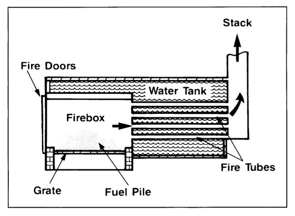
Figure 1. A typical hot-water heating system.
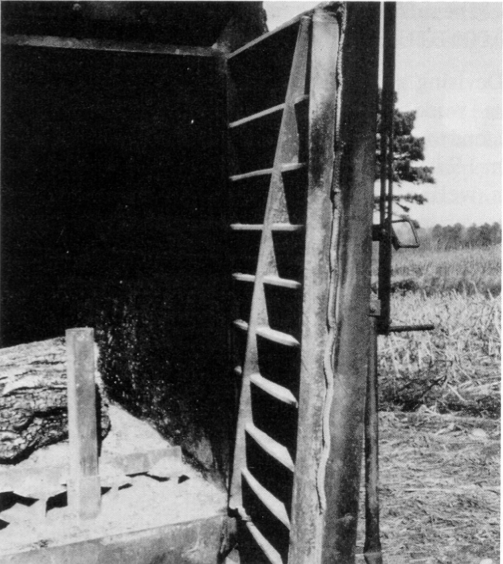
Figure 2. Doors must be water cooled to prevent the intense heat from warping them.
The Water Tank
The most visible part of a hot-water system is the water tank. Standard tanks suitable for hot-water heating systems are available in a variety of sizes, capacities, and wall thicknesses. Underground tanks have thicker walls than the above-ground variety, making them much better for welding. Given a choice, it is better to use a short, large-diameter tank than a long, thin one because a shorter tank has less surface area, reducing heat loss and cost of insulation. Table 3 gives dimensions and capacities for a wide range of standard petroleum storage tanks.
| Capacity (gallons) | Diameter | Length |
| 500 | 48 in | 64 in |
| 560 | 42 in | 92 in |
| 1,000 | 491⁄2 in | 10 ft |
| 2,000 | 64 in | 12 ft |
| 4,000 | 64 in | 24 ft |
| 6,000 | 8 ft | 16 ft 1 in |
| 8,000 | 8 ft | 21 ft 4 in |
| 10,000 | 8ft 101⁄2 ft |
26 ft 1 in 15 ft 8 in |
| 12,000 | 8 ft 101⁄2 ft |
31 ft 11 in 18 ft 7 in |
| 15,000 | 8 ft 101⁄2 ft |
39 ft 11 in 23 ft 4 in |
| 20,000 | 101⁄2 ft | 31 ft |
| 25,000 | 101⁄2 ft | 38 ft 9 in |
| 30,000 | 101⁄2 ft | 46 ft 6 in |
Although it is best to use a new tank, many successful systems have been built with used tanks. Used oil storage tanks can often be obtained simply for the asking. If you decide to try a used tank, inspect it thoroughly for holes or thin spots. Also, inquire what liquid has been stored in the tank. Caution: Never weld or cut on a tank that you suspect contained any flammable material unless it is thoroughly cleaned and ventilated. One method for removing oil or gasoline residue from a large tank is to mix about 2 pounds of detergent per thousand gallons of capacity with enough water to dissolve it and pour this solution into the tank. Then fill the tank completely full of water and let it sit for several days before draining it and beginning to work on it.
Heat Storage Capacity
As mentioned in an earlier section, one measure of a system's capacity is its heat storage capacity. Water is one of the least expensive and most easily moved and controlled substances. It is also one of the best heat storage media known. Water can store four or five times as much heat as stone, up to ten times as much as most metals, and about four times as much as air per unit of weight. Its only disadvantage is that it cannot store heat at temperatures above 212°F unless it is under pressure. This limits its usefulness for high-temperature applications. However, for space-heating applications in greenhouses and other agricultural, commercial, or residential application, this limitation is usually not a problem.
By definition, one British Thermal Unit (BTU) is the amount of heat required to raise the temperature of 1 pound of water 1°F. A gallon of water weighs approximately 8.3 pounds, so the heat energy required to raise the temperature of a gallon 100°F is:
8.3 pounds x 100°F = 830 BTU
By comparison, raising the temperature of 8.3 pounds of gravel 100°F would require only about 166 BTU.
As stated before, water cannot be heated to above 212°F at atmospheric pressure. This temperature determines the upper limit to the amount of heat that unpressurized water can store. The lower limit is established by the desired load temperature. For example, if a greenhouse is to be kept at 65°F, then that temperature is the lower limit. The difference between the upper and lower limit,
212°F - 65°F = 147°F
indicates how much usable heat a given volume of water can hold.
Actually, it is not practical to draw the storage temperature down to the lower limit. The rate of heat transfer to the load (for instance, from radiators to the air inside a greenhouse) is greatly reduced as the temperature of the heated incoming water approaches the load air temperature. For that reason it is desirable to maintain the lower water storage temperature at least 35°F above the desired load temperature. In the previous example, therefore, the lower limit temperature would be 100°F and the temperature difference would not be 147°F, but
212°F - (65°F + 35°F) = 112°F
Therefore, the storage temperature range of the water is limited to 112°F. Using this information as a guide, we can now determine how much storage capacity is needed.
If the desired heat load is determined to be 200,000 BTU per hour and it is desired to have 6 hours of heating available after the fire goes out, the quantity of water must be adequate to store:
200,000 BTU/hr x 6 hr = 1,200,000 BTU
Raising one pound of water 1°F requires 1 BTU. Each pound of water can store only 112 BTU. Therefore the amount of water required is:
1,200,000 BTU ÷ 112 BTU/lb = 10,714 lb
Since water weighs 8.3 pounds per gallon, 10,714 pounds of water is equal to 1,291 gallons.
In practice, the maximum water temperature seldom exceeds 200°F; therefore, a storage capacity slightly greater than 1,291 gallons is needed.
These calculations assume that no heat is lost from the tank or from the pipes that carry the water to and from the load. These losses can be significant, depending on how well the pipe is insulated, the distance from the tank to the load, and the outside temperature.
It is a very good idea to install a thermometer in the outlet line of the tank. It will give an accurate indication of the water temperature inside the tank. A drop in water temperature of more than 20°F per hour is a good indication that the water tank is too small, since the purpose of a hot-water system is to provide a constant source of heat without need to stoke the fire constantly.
It is also a good idea to install a thermometer in the lines on both sides of the load – for instance, on the inlet and outlet lines of the radiator or bank of radiators. This makes it possible to determine not only how much energy is lost between the tank and the load but also how efficiently the radiators extract heat from the water.
For optimal system design, the storage capacity must be based on the maximum rated burner output, the required heat load, and the maximum length of time desired between fuel loadings. The following discussion illustrates how these three factors interact.
Suppose, as in the example above, that the required average heat load is 200,000 BTU per hour. This means that during a typical hour of operation, 200,000 BTU of heat is required. It is probable that in the middle of a very cold night, the amount of heat required would exceed this amount. But in order to have sufficient heat available, the burner capacity must at least equal the average load plus the losses. From a practical standpoint, it is advisable for the burner to be rated at one-and-one-half to two times the average heat load. A larger burner can produce heat for storage as well as for immediate use at times when the load is average.
Besides the energy stored in the hot water (tank storage), it is also possible to store heat energy in the system in the form of unburned wood. This is called firebox storage. In anticipation of a very cold night, a greenhouse operator might stoke the system throughout the day to gradually raise the water temperature close to 212°F. Even though the water is already holding close to its maximum amount of heat, the operator might again fill the firebox just before leaving for the night. This additional fuel adds energy to the system. The burning fuel might just replace the outgoing heat and thus maintain the high water temperature. If the additional fuel adds too much heat too quickly, however, the water in the tank will boil and energy will be wasted as steam.
It is unlikely that a hot-water system during actual operation would be subjected to very large swings in load. In other words, it would not be required to produce the maximum output one hour and none the next. Rather, gradual increases and decreases normally occur during the day as the outside temperature and many other factors change. On the other hand, the heat supplied to the system from the fire is normally rather sporadic, depending on how much and how often fuel is added. The value of a hot-water system is based partly on its ability to store heat energy quickly but release it slowly at a controlled rate.
If the burner produces more heat than is being used by the system, the extra heat will be stored, provided that the storage capacity has not been exceeded. Exceeding the storage capacity causes the water to boil. When that happens, the excess heat produced passes out of the system in the form of steam. The energy required to boil the water is simply wasted. Frequent boiling in a hot-water system indicates that the burner is too large or is being fired too often or that the heat storage capacity of the system is too small.
If the heat storage capacity is inadequate, one solution is to add another tank. A tandem tank is normally positioned as close to the main tank as possible and connected by an inlet and outlet pipe and pump (Figure 3). In this way, the storage capacity may be quite easily increased without disturbing the rest of the system. Water must always be pumped continually between the two tanks to distribute the heat uniformly. This can be done by adding an extra pump or using part of the flow from an existing pump if it has excess capacity.
Hot-water system are not steam systems; that is, there is never any pressure in the system other than that produced by the pumps. The hot-water tank must be vented to prevent pressure from building up when the water is heated and expands or turns to steam. An unvented storage tank is extremely dangerous. At least two vents are required on the top of the tank. Better yet, the manhole that is usually cut into the top of the tank during construction can be left open but covered with a piece of sheet metal.
Insulation
It is necessary to insulate the tank and all pipes to prevent the escape of heat. For outdoor tanks, sprayed-on polyurethane insulation is suitable, especially if it is painted and protected from direct exposure to fire and sunlight. A coating 1-inch thick, yielding an R-7 insulation rating, costs about $1 per square foot. For example, for a 2,000 gallon tank 64 inches in diameter and 12 feet long, the insulation will cost approximately $250. Table 4 gives the estimated insulating value of different thicknesses of polyurethane on tanks.
| Insulation Thickness (inches) | "R" Value | Heat Loss (BTU/hr)1 | Monthly Cost of Lost Energy2 | Insulation Cost3 |
| 0.0 | 0.5 | 200,000 | $384.00 | $0 |
| 0.5 | 4.0 | 25,000 | 48.00 | 500 |
| 1.0 | 7.5 | 13,300 | 25.54 | 1,000 |
| 2.0 | 14.5 | 6,900 | 13.25 | 2,000 |
| Note: The data in this table are based on a tank capacity of 15,000 gallons and a surface area of 1,000 square feet. 1 Assuming a 100°F difference in water and ambient temperatures. 2 Assuming that wood costs $40 per cord. 3 Assuming an applied cost of $1 per square foot per inch of thickness. |
||||
This table shows that the cost of applying a minimum amount of insulation can easily be justified by the savings in energy costs. The added cost of insulation greater than 1⁄2 inch thick, however, is hard to justify.
One alternative is to place the system under a shed-type roof where it can be insulated with relatively inexpensive fiberglass batts. The fiberglass, which may have aluminum foil backing, can be held in place with large mesh chicken wire. The cost of the shed, insulation, film, wire, and labor may be more than that of sprayed-on polyurethane insulation, but this type of insulation will probably last much longer and yield a better R value.
Rust Prevention
It is advisable to use some type of rust prevention measures to protect the inside of the tank and pipes from corrosion. There are a number of commercial chemicals available intended for use primarily in high-temperature boilers. Some of these would be quite expensive to purchase in the amount necessary to protect a moderate-sized hot-water system.
One method that has been found adequate in hot-water systems is to add certain relatively inexpensive chemicals to raise the pH of the water. Among these are potassium carbonate, sodium carbonate (washing soda) and sodium hexa meta phosphate (Calgon). These chemicals prevent corrosion by coating the metal walls of the systems. Of the chemicals mentioned above, Calgon works best. It can be purchased at most grocery stores. Use 5 pounds for each 1,000 gallons of water. Under normal conditions, none of these chemicals will degrade and consequently will remain active in the system for a long time.
Firetubes
Although some heat passes to the water through the walls of the firebox, the main path of heat from the fire to the water is through the firetubes. Most systems are designed so that the hot gases given off by the fire pass through a series of firetubes that run from one end of the storage tank to the other. In many systems the gases are made to pass through the tank more than once.
It is very important that the number and size of the firetubes be sufficient that most of the heat is transferred from the hot gases to the water before the gases escape. As a rule of thumb, about 1 square foot of heat exchange area is required for each 2,000 BTU of rated output. For example, if a system is sized to produce 200,000 BTU per hour, approximately 100 square feet of heat exchange area is needed. This area can include the water-cooled surface of the firebox as well as the firetubes themselves. Both of these areas are often called the fireside surface.
The outside diameter of the firetubes is used to calculate the area. Table 5 lists several commonly used sizes of standard pipe along with their actual outside diameter and the number of running feet required to yield 1 square foot of surface area.
| Nominal Pipe Size (inches) | Outside Diameter (inches) | Linear Feet Per Square Foot of Outside Area |
| 1/2 | 0.840 | 4.55 |
| 3/4 | 1.050 | 3.64 |
| 1 | 1.315 | 2.90 |
| 1 1/4 | 1.660 | 2.30 |
| 1 1/2 | 1.900 | 2.01 |
| 2 | 2.375 | 1.61 |
| 2 1/2 | 2.875 | 1.33 |
| 3 | 3.500 | 1.09 |
| 3 1/2 | 4.000 | 0.95 |
| 4 | 4.500 | 0.85 |
| 4 1/2 | 5.000 | 0.76 |
| 5 | 5.563 | 0.67 |
| 6 | 6.625 | 0.58 |
The proper size of pipe to use depends on a number of factors. In the example system with a capacity of 200,000 BTU per hour, 100 square feet of heat exchange area is required. From Table 1, the recommended firebox volume is 9 cubic feet. A suitable firebox having this volume would be one that is 11⁄2 feet long, 2 feet wide, and 3 feet tall. The surface area of this firebox is 27 square feet (including the water-cooled door). Therefore, the firebox would provide 27 square feet of the needed 100 square feet. The firetubes must provide the other 73 square feet.
To find the length of pipe of a given diameter needed to provide the desired surface area, multiply the numbers in the third column of Table 5. For instance, if you select 11⁄2-inch pipe, multiply 73 linear feet by 2.01:
73 ft x 2.01 ft/sq ft = 146.72 ft
About 147 linear feet of 11⁄2-inch pipe is required to get 73 square feet of heat exchange area. On the other hand, if you use 3-inch pipe you need only about 80 feet:
73 ft x 1.09 ft/sq ft = 79.73 ft
Which size is best? Considered strictly from a cost standpoint, there is not much difference between 147 feet of 11⁄2-inch pipe and 80 feet of 3-inch pipe. However, it is much easier to weld the larger pipe. Also, it will be necessary to clean the inside of the pipe from time to time to remove ash, soot, and other deposits. Cleaning a shorter length of larger pipe is easier. The larger number of smaller pipes, however, would be somewhat more efficient in heat transfer. Experience has shown that 2- to 3-inch pipe works best overall.
Deposits of ash in the firetubes will greatly reduce the rate of heat transfer. It is good to have some way to determine how well they are working. One of the best and least expensive methods is to position a high-temperature thermometer at the point where the gases leave the firetubes and start up the stack. The closer the temperature of the water, the more effectively the firetubes are transferring heat. A gas temperature of 300 to 350°F indicates efficient heat transfer. A gas temperature of more than 450°F indicates that the heat exchange area is too small or the firetubes have become coated.
Stratification
A curious condition sometimes occurs in medium to large systems. Even though the firebox is constantly stoked and the water can be seen boiling from the top of the tank, the temperature of the water being drawn from the tank for distribution is only 170 to 180°F. This situation occurs in systems where the inlet and outlet are near the bottom of the tank and there is no auxiliary circulation pump to keep the water moving. The condition is called stratification and results when water at different temperatures separates into distinct layers, with the warmest water remaining at the top. Stratification can occur in any system but is usually more pronounced in large ones.
The density of water at 100°F is about 3.5 percent greater than at 200°F. Just like air, hot water rises and cold water sinks. To prevent stratification, the water must be kept moving. One method is to connect the return pipes at the top of the tank above the firebox (the hottest part of the system) and draw water from the lower part of the tank at the other end. The problem with this approach is that the distribution pumps may not run all the time and stratification can occur when the pumps are turned off.
A better solution is to install a continuously running auxiliary circulation pump to move water from the coldest to the hottest part of the tank. The constant mixing of the water will prevent stratification. The circulation pump need not be large, as there is very little head to overcome. It should be capable of pumping 0.2 to 0.5 times the system capacity per hour. For instance, a 2,000 gallon system should have a pump capable of pumping 400 to 1,000 gallons per hour. A 1⁄6 to 1⁄2-horsepower electric pump is usually adequate.
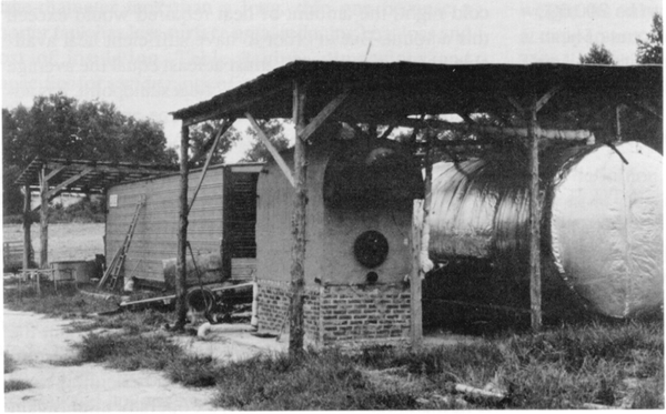
Figure 3. An additional tank will increase storage capacity.
The Pump and Piping System
Piping
In addition to storing heat, water is used to transport the heat to the place where it is used. The distribution pump must be correctly sized for the job. If the pump is too small, it will not pump sufficient heat to the load. If it is too large, it will waste energy. The sizing of the pump is a rather complicated matter because it depends on a number of interrelated factors. These include the size of the load, the distance between the tank and the load, the number of different heat exchangers in the system, and the size of pipe used. Table 6 gives pipe sizes for various heat loads. These flow rates and pipe sizes are calculated assuming the normal 25°F temperature drop as the water passes through the heat exchanger.
| Load (BTU/hr) | Flow Rate (gal/min) | Steel Pipe Diameter (inches)1 | |
| 100 feet | 300 feet | ||
| 100,000 | 8 | 1 1/4 | 1 1/2 |
| 200,000 | 16 | 1 1/2 | 2 |
| 300,000 | 24 | 2 | 2 1/2 |
| 400,000 | 32 | 2 1/2 | 2 1/2 |
| 500,000 | 40 | 2 1/2 | 3 |
| 750,000 | 60 | 3 | 3 |
| 1,000,000 | 80 | 3 | 4 |
| 1,500,000 | 120 | 4 | 4 |
| 2,000,000 | 160 | 4 | 4 |
| 1 For CPVC pipe, the next smaller size is adequate | |||
Except for residential applications, most hot-water systems supply heat to more than one location. For example, several separate greenhouses or curing barns may draw heat from the same system. The hot water is carried to each load by large main distribution and return lines. Each load has its own pump and is connected to the main lines in parallel fashion, making it independently controllable (Figure 4). Each parallel connection must have a check valve to prevent reverse flow when heat is not needed.
Pumps are normally rated by the number of gallons per minute they will deliver at a certain head or total resistance. This total resistance is the sum of the resistances of each separate part of the system that the water passes through in its circuit to and from the pump. The resistance is usually expressed as a number of feet of "head," although it could just as well be expressed in pounds per square inch. The head is the hypothetical height of water that the pump must work against; the greater the head, the greater the resistance.
As the resistance increases, the flow rate decreases. For instance, a certain pump may be rated at 50 gallons per minute at 10 feet of head but only 15 gallons per minute at 30 feet of head. One foot of head is equivalent to 0.43 pounds per square inch (psi). In choosing a pump, it is important to select one rated for hot-water service at temperatures up to the maximum expected.
Many systems use standard steel pipe and threaded connections. They are relatively inexpensive and are suitable for hot-water service. Some of the newer systems use plastic pipe. Polyethylene (black plastic) and PVC pipe will not hold up under prolonged hot-water use at moderate pressures. However, two types of plastic pipe – CPVC and Polybutylene – are designed for hot-water use. CPVC is a rigid plastic pipe similar to PVC. If CPVC pipe is used, all fittings – such as connectors, reducers, and elbows – must also be made of CPVC. Polybutylene pipe also requires special connectors but is flexible and considerably easier to work with. It is not yet readily available in sizes larger than 1 inch, however.
Pipe Insulation
It is essential for the sake of efficiency that distribution pipes both to and from the load be insulated. The amount of heat that can be lost from a length of pipe is substantial and depends on a number of factors. These include the temperature of the water passing through the pipe, the temperature and motion of the air surrounding the pipe, the type of pipe material, and the surface condition and thickness of the pipe wall. Uninsulated hot-water distribution pipe can lose from several hundred to several thousand BTU per hour, depending on conditions and length.
If the pipes are to be run above ground, a fiberglass batt covering protected from rain with several layers of sunlight-resistant plastic film will be sufficient. Any insulation, especially fiberglass, that is soaked with water will lose almost all of its insulating properties. Plastic foam pipe insulation in the form of split tubes also works well if protected from sunlight.
It is much more difficult to insulate pipe when it is run underground. it is very poor practice to simply bury pipe in the ground without insulation, because wet, cold soil is an extremely good conductor of heat. Most plastic foam insulation, such as the split-tube type, is made of closed-cell foam, which means that it will not become soaked with water and therefore will retain its insulating properties underground. If you must run pipe underground, make certain that the ground remains as dry as possible.
The sprayed-on polyurethane insulation commonly used on tanks can also be used to insulate underground pipes because it is of the closed-cell type. To use this method, a trench 4 to 6 inches wide and 12 to 14 inches deep is dug. The pipes are supported 2 or 3 inches off the bottom and 4 to 5 inches of insulation is sprayed into the trench, completely surrounding and covering the pipes. After the insulation sets up, the trench is filled with soil.
No matter what method is used to insulate the pipe, it is important to remember to insulate the return pipe as well as the pipe going to the load. Even though much of the heat has been removed from the returning water, any energy lost from the pipe must be replaced. It takes the same amount of heat to raise 1 pound of water from 80 to 85°F as from 200 to 205°F.
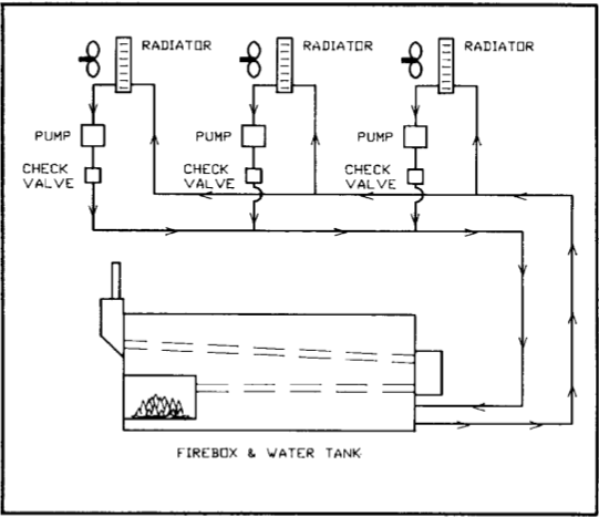
Figure 4. Typical layout of a multiload system.
The Water-to-Air Heat Exchanger
An important part of any hot-water system is the heat exchanger or radiator. If it is not sized correctly or the airflow through it is insufficient, the performance of the system can suffer greatly. Fortunately, heat exchangers come in many different sizes. A wide range of commercial radiators designed specifically for hot-water systems are available. Most of these can operate at water pressures as high as 50 to 60 psi and have threaded fittings for connecting them to the distribution system.
A very suitable alternative to a commercial radiator is a new or used automobile radiator. These are available in many different sizes and can be purchased at most junk yards and parts supply houses. Many dealers have new radiators for older cars that they might be willing to sell at reduced prices. Automobile radiators, however, are not generally suitable for water pressures higher than 15 to 20 psi. This limitation should not be a problem if the pump and distribution pipes are sized correctly. Automobile radiators, however, will need some modifications, including plugging of the fill and overflow holes and modifying the transition from the rubber hose fitting to the distribution pipe.
The heat transfer characteristics of any radiator are dependent on a number of factors. The most important are the flow rate and temperature of the water and air streams. In general, the greater the temperature difference between the water and the air, the more rapidly heat is transferred. Also, the more water and air passing through a radiator, the greater the amount of heat transferred. Factors such as the design of the radiator, the number and distribution of fins, and the material from which the radiator is made are also important. For example, under typical operating conditions many commercial heat exchangers designed specifically for hot-water service deliver about 20,000 BTU per hour for each square foot of face area.
Since most radiators have similar heat transfer characteristics, the deciding factor in determining capacity is physical size. Tests have shown that automobile radiators can transfer between 16,000 and 20,000 BTU per hour per square foot of face area (from 140°F water to 70°F air). For example, a radiator that is 11⁄2 feet wide by 2 feet tall has 3 square feet of area. It could therefore transfer between 48,000 and 60,000 BTU per hour.
The Control System
The controls for a hot-water system are quite simple. They normally consist of a thermostat connected to a relay that controls a separate pump for each load. The motor for the fan that blows air through the radiator may also be connected to the same relay since it need not run when the pump is off. This arrangement allows each load to be controlled independently. In some systems the pump is allowed to run continuously and the fan is cycled by the thermostat.
Most of the larger systems require a draft fan as described earlier to ensure proper combustion. The draft fan normally runs whenever there is a fire in the firebox. When there is no fire it should not be allowed to run and can be manually shut off. However, this arrangement does not work when the system is stoked and then left unattended for long periods, such as overnight. When the field has been consumed, the fan will continue to run, drawing cold air through the firetubes and thus cooling the water. It is important to remember that the firetubes are heat exchangers and that heat will flow from the hot water to the cooler tubes as well as vice versa. One solution is to install a thermostat in the smoke stack to stop the fan when the temperature drops to about 200°F – that is, when there is no more heat passing into the water. A manual override may be needed in order to start a fire when the system is cold.
Fuel
Wood is a great fuel. Compared to most other fuels it is inexpensive, can be stored quite easily, can be used in a variety of shapes and sizes, and is widely distributed in North Carolina. It is estimated that there are over 14 million tons of wood per year available in this state for fuel.
Although it is a good fuel, wood does have drawbacks. It contains less energy per pound than most other fuels. The amount of usable energy in a sample of wood can vary widely, depending on the moisture content and species.
A growing tree is typically one-half water. When the tree is cut, the wood begins to lose moisture to the surrounding air. Wood that has been freshly cut and contains a high percentage of moisture is often referred to as green wood. After it has dried for a period of time (usually several months or more, it is called seasoned or dry wood. As the wood loses moisture, it gradually approaches a moisture content between 12 and 15 percent. This value is called the equilibrium moisture content (EMC). The actual percentage is determined by the long-term average of the temperature and relative humidity of the air surrounding the wood. Although it would be desirable, it is not practical to remove all the water from fuel wood.
The moisture content of fuel wood is usually expressed as a percentage of the total wet weight. For example, if a certain piece of wood weighs 7 pounds and 6 ounces (118 ounces) but upon bone drying weighs only 5 pounds 4 ounces (84 ounces), the original moisture content of the wood is then expressed as:
118 - 84 = 34 oz of water
34 ÷ 118 = 0.288 or 28.8 percent
This means that the water made up 28.8 percent of the weight of the wet wood. Moisture content expressed as a percentage of the wet weight is often abbreviated m.c.w.b. (moisture content, wet basis).
The effective heat content of wood fuel is lowered by the moisture it contains in two ways. First, the more water there is in a given piece of wood, the less wood it contains. Second, part of the fuel value contained in the wood is used to evaporate the water when the wood is burned. Approximately 1,000 BTU of heat energy is required to evaporate each pound of water in the wood. A piece of wood contains the same amount of energy whether green or dry. Green wood burns poorly, however, because some of the energy is used to evaporate the excess water. Table 7 gives the net energy value (heating value) of wood at various moisture contents.
| Moisture Content Wet Basis (percent) | Heating Value (BTU per pound) | Weight (pounds per cord) |
| 0 | 8,600 | 2,960 |
| 5 | 8,120 | 3,116 |
| 10 | 7,640 | 3,289 |
| 15 (properly seasoned) | 7,160 | 3,482 |
| 20 | 6,680 | 3,700 |
| 25 | 6,200 | 3,947 |
| 30 | 5,720 | 4,229 |
| 40 | 4,760 | 4,933 |
| 50 (green) | 3,800 | 5,920 |
Notice that properly seasoned wood has an 88 percent high heating value content (by weight) than green wood. Note also that green wood weighs nearly twice as much as seasoned wood. A 1-pound piece of green wood weighs only 0.59 pounds when seasoned. A chunk of wood burned when "green" gives only about half as much heat as it does when properly seasoned. That is why it is very important that fuel wood be properly seasoned. For wood left in whole log form, 12 inches in diameter or smaller, as much as a full year may be required to season it properly. Ideally, wood to be used during the winter should be harvested during the previous summer and allowed to dry. In that way, the wood is dried by summer heat rather than by part of the energy contained in the wood itself. Of course, wood allowed to season will dry much faster if split and stored under a shed.
Density
Experience has shown that oak is a better wood for heating than pine because oak is much more dense. A cubic foot of air-dried oak weighs around 42 pounds, whereas a cubic foot of air-dried loblolly pine weighs about 32 pounds. Oak, then, is about 32 percent more dense than pine, and a cord of oak generally contains about one-third more energy than a cord of pine. This is an important consideration since fuel wood is normally bought and sold by the cord, which is a measure of volume, not weight. The important thing to remember is that pound for pound, almost all wood species contain about the same amount of energy. You get more pounds of wood – and therefore more heat energy – in a cord of denser woods.
Other Fuel Considerations
A very widely held belief is that some softwoods such as pine produce more tar or creosote than hardwoods. Numerous tests have shown that this is not the case. In fact, recent tests shown no measurable difference in tar yield between pine and oak. If wood is burned properly, no tar should be formed.
Besides the more traditional forms of wood fuel such as chips and cordwood, split or round, scrap wood may be available. It may be in the form of wood waste from furniture plants or scrap lumber from building or demolition sites. All these types of wood are fine to use. One very important thing to remember, however, is that you should never burn any type of treated wood. Wood treated with coal tar creosote, such as railroad ties or utility poles, burns vigorously and gives off a dense, black, toxic smoke. Wood treated with such compounds as chromated copper arsenate (CCA) is usually greenish yellow or tan in color and gives off a very toxic smoke when burned. Handling or breathing the ashes of CCA-treated lumber can cause acute poisoning. Even a relatively small amount of treated wood mixed with untreated lumber can cause serious problems. Be careful and know the type of fuel you are using.
Fuel Cost Comparisons
A comparison of wood and number 2 fuel oil shows that the energy content of various fuels, usually called the specific energy, can vary widely. For example, number 2 fuel oil contains about 19,000 BTU per pound, whereas bone-dry wood contains approximately 8,600 BTU per pound. On a pound-for-pound basis, fuel oil has over twice the energy of wood. Comparing the specific energy of wood and fuel oil, however, tells only part of the story.
At $1 per gallon, a pound of fuel oil costs about 13 cents. At $40 per cord, a pound of white oak wood costs less than one cent. Table 7 shows that a pound of properly seasoned wood contains about 7,160 BTU.
The following calculations compare these fuels on the basis of cost per million BTU:
Fuel Oil: $.13/lb ÷ 9,000 BTU/lb x 1,000,000 = $6.84 per million BTU
Wood: $.008/lb ÷ 7,160 BTU/lb x 1,000,000 = $1.12 per million BTU
These calculations show that the cost of fuel oil is more than six times the cost of the wood needed to produce the same amount of heat. Thus wood has a great cost advantage over most other fuels.
Objections to the use of wood as an energy source are usually related to convenience. In very cold weather, most wood-fueled hot-water systems must be stoked at least once during the night. There are certainly disadvantages in getting up at 2am to stoke a system. On the other hand, there is definitely a cost advantage to using wood.
Wood System Cost and Efficiency
When considering a wood-fueled hot-water system, one should not overlook two other important comparisons. One is system costs and the other is efficiency. The cost of installing a correctly sized system depends on individual needs. For instance, most oil or gas systems are sized for and installed in individual greenhouses, whereas one large hot-water system can accommodate many greenhouses or several tobacco curing barns along with other buildings and a residence.
The second aspect to consider is the efficiency of the system. Efficiency, which is usually expressed as a percentage, is a measure of how well the sytem converts and delivers the chemical energy stored in the fuel into usable heat energy. The percentage describes the proportion of the energy input that is actually converted and applied as usable heat. It is important to realize that overall efficiency is also influenced by how well the system delivers the heat. Said another way, it is not enough for a system to burn the fuel efficiently, but the heat must also be delivered with minimum loss to the place where it is to be used. The following example illustrates how overall efficiency is calculated:
A wood-fueled hot-water heating system is known to burn 200 pounds of air-dried wood per hour, during which time 2,300 gallons of heated water passes through the greenhouse heat exchangers with a 45°F drop in temperature. The temperature of the water in the storage tank remains constant.
The energy content of the air-dried wood is 7,160 BTU per pound. Thus, the energy released by burning 200 pounds per hour is:
7,160 BTU/lb x 200 lb/hr = 1,432,000 BTU/hr
By definition 1 BTU is the amount of heat energy required to raise the temperature of 1 pound of water 1°F. One gallon of water weighs 8.3 pounds; therefore the heat energy delivered by the system is:
2,300 gal/hr x 8.3 lb/gal x 45° = 859,050 BTU/hr
The system efficiency is the ratio of the energy output to the energy input:
Overall efficiency, E = energy output of the system ÷ energy input to the system
E = 859,050/1,432,000
E = 0.60 or 60%
These calculations assume that the temperature of the water in the storage tank remains constant and that the 45°F temperature drop includes the losses in the lines carrying the water to and from the greenhouse.
Without some rather involved tests, it is very difficult to determine the exact efficiency of a heating unit. However, Table 8 shows that typical efficiencies of common heating systems vary widely.
When investigating the overall cost of heating with various types of fuels it is very important to compare system efficiencies, especially if there is very little cost difference per million BTU between two alternative fuels. System efficiency has less influence on which choice is best as the cost difference between the fuels increases. At present, there is sufficient cost difference between wood fuel and other commonly used fuels to make wood systems cost effective even with fairly low efficiencies. If properly designed for maximum efficiency, wood systems are clearly less costly to operate.
| System Type | Efficiency (percent) |
| Electric resistance heater | 98 |
| LP or natural gas heater | 75 |
| Oil furnace | 65 |
| Wood-fueled hot-water system | 60 |
The values in Table 9 are based on the efficiencies shown in Table 8 and on the assumptions that a cord of seasoned wood weighs 3,492 pounds and contains 7,160 BTU per pound, that fuel oil contains 138,000 BTU per gallon, and that LP gas contains 86,000 BTU per gallon. The costs of owning and operating the different systems are not included.
| Fuel Costs | ||
| Wood (per cord) | Fuel Oil (per gallon) | LP Gas (per gallon) |
| $10 | $0.06 | $0.043 |
| 20 | 0.12 | 0.086 |
| 30 | 0.18 | 0.129 |
| 40 | 0.24 | 0.172 |
| 50 | 0.30 | 0.215 |
| 60 | 0.36 | 0.258 |
| 70 | 0.42 | 0.301 |
| 80 | 0.48 | 0.344 |
| 100 | 0.60 | 0.430 |
| 140 | 0.84 | 0.602 |
| 180 | 1.08 | 0.774 |
| 200 | 1.20 | 0.860 |
| 250 | 1.50 | 1.075 |
| 300 | 1.80 | 1.290 |
| 400 | 2.40 | 1.720 |
| 500 | 3.00 | 2.150 |
For Further Information
It is hoped that this publication has helped you gain a better understanding of how a properly designed hot-water system operates and to determine whether you can benefit by installing one. If you choose to build your own system, as many have done, applying the guidelines and procedures given in this publication should help you construct a highly efficient system. If you choose to purchase one of the commercially available units instead, this information should help you to choose the best system for your application and to operate it efficiently.
For more information on wood energy applications, see Extension publication AG-363, Wood Energy Guide for Agricultural and Small Commercial Applications. In addition, you may find the following publications helpful:
Wood Energy Information Guide. Raleigh, NC: Energy Division, North Carolina Department of Commerce, 1982.
Wood Energy for Small-Scale Power Production in North Carolina. Raleigh, NC: Energy Division, North Carolina Department of Commerce, 1978.
Decision Maker's Guide to Wood Fuel for Small Industrial Energy Users. Golden, Colo.: Solar Energy Research Institute, 1980.
Wood as Energy, Agricultural Issues Overview Number 5. Washington, DC: National Agricultural Library, US Department of Agriculture, 1984.
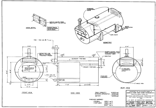
Wood-fired hot-water heater - 1,000,000 BTU per hour.
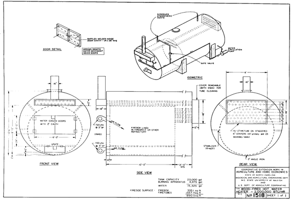
Wood-fired hot-water heater - 2,000,000 BTU per hour.
Publication date: Jan. 1, 1995
AG-398
N.C. Cooperative Extension prohibits discrimination and harassment regardless of age, color, disability, family and marital status, gender identity, national origin, political beliefs, race, religion, sex (including pregnancy), sexual orientation and veteran status.