Information presented in manufacturer’s charts are based on average operating conditions for relatively new equipment. Discharge rates and application rates change over time as equipment gets older and components wear. For solid or semi-solid application equipment, application rates and patterns may vary depending on forward travel and/or PTO speed, gear box settings, gate openings, operating pressures, spread widths, and overlaps.
Equipment should be calibrated on a regular basis to ensure proper application rates and uniformity. Calibration is a simple procedure involving collecting and measuring the material being applied at several locations in the application area. Calibration helps ensure that nutrients from animal waste are applied efficiently and at proper rates.
Solid or semi-solid (slurry) applicators can be calibrated by one of two methods: load-area method, and weight-area method.
Load-Area Method
To use the load-area method, you must know the spreader capacity. Spreader capacity is normally rated by the manufacturer and often is indicated on the application equipment. Liquid spreaders are normally rated in gallons while semi-solid spreaders are rated in either bushels or cubic feet.
As the name implies, the load-area method involves applying a full load to a measured area. For ease of measurement, it is best to use a rectangular field pattern. For PTO-driven spreaders, application rate is dependent on ground speed so a uniform speed must be maintained throughout the swath length. Ground-driven applicators apply reasonably uniform rates independent of ground speed. Refer to fact sheet AG-553-5 for detailed calibration procedures.
Weight-Area Method
The weight-area method is often used for solid and semi-solid spreaders. The procedure involves measuring the spreader discharge over a small measured area. The application rate is determined by dividing the collected material (weight) by the collection area.
Weight-Area Method Calibration Procedure
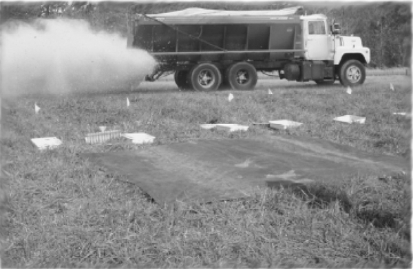
- Obtain a tarp or plastic sheet of about 100 square feet (9’ × 12’, 10’ × 10’, 10’ × 12’, etc.) and measure for exact surface area (length × width).
- Weigh the tarp using a set of spring-tension or platform scales.
- Spread the tarp and pin on the field surface at each corner with a tent stake or long nail through the eyelets.
- Operate the spreader over the center of the tarp at the speed normally driven when applying manure on the field.
- Make two additional passes on two opposite sides of the center of the tarp at the normal spreader overlap spacing.
- Remove and fold the tarp being careful not to spill any collected material. Weigh the tarp and manure (gross weight).
- Subtract the empty tarp weight from the gross tarp plus manure weight to obtain the weight of manure applied.
- Divide the amount of manure collected (pounds) by the tarp area (square feet) and multiply this value by 21.8 (43,560 ft2/ac divided by 2,000 lbs/ton) to convert pounds per square foot to tons per acre.
- If the application rate needs to be adjusted, make the necessary changes (spreader settings, speed, or both) and repeat the procedure until the desired application rate is obtained.
Spreader Pattern Uniformity
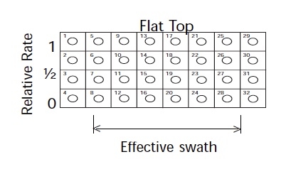
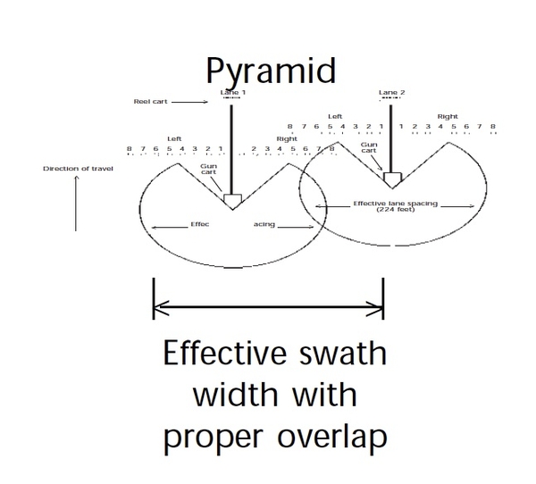
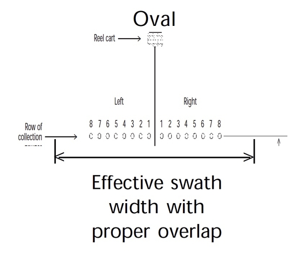
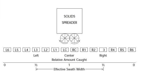
Determination of spreader uniformity is an important component of spreader calibration. The pattern shape and uniformity determines the overlap required for uniform application. One of the pattern shapes shown in Figure 1a, 1b, and 1c is required for a uniform application.
To determine the uniformity of spread and the amount of overlap needed:
- Place a line of small pans or trays equally spaced (2 to 4 feet apart) across the spreader path (See Figure 2). Label the pans chronologically as left or right from the center pan. Center pans may need to be shifted slightly out of the spreader wheel tracks. (Pans should be a minimum of 12 by 12 inches, no more than 24 by 24 inches, and 2 to 4 inches deep.)
- Make one spreader pass directly over the center pan at normal operating speed and spreader settings.
- Record
- spinner PTO speed,
- flow divider delivery point onto the spinners, and
- the spreader gate setting.
- Record
- Weigh and record the contents caught in each pan.
- The effective spread width is found by locating the pan on either side of the path center where the contents caught in the container is one-half the amount caught in the center pan.
- The distance between the two pans on either side of the center (in Number 4) is the effective width. The outer fringes of the coverage area beyond these points should be overlapped on each subsequent path.
Calibrating Solid and Semi-Solid Manure Spreaders Using the Weight-Area Method
-
Spread a tarp or plastic sheet over the ground surface and secure with pins or small weights. The tarp should have at least 100 square feet (9’ × 12’, 10’ × 10’, etc.) of surface area.
- width __________ × length __________ = area __________ ft2
-
Start applying manure downrange of the tarp and spread directly across the center of it in a manner similar to the regular spreading patterns and settings of the applicator (speed, spreader settings, overlap).
-
Forward speed, gear, or throttle setting
Trial 1 Trial 3 Trial 3 - PTO speed or setting
Trial 1 Trial 3 Trial 3 - Spreader gate setting
Trial 1 Trial 3 Trial 3
-
-
Transfer the manure collected on the tarp into a weighing container and weigh using an accurate set of spin- tension or platform scales.
- Empty weight of weighing container
Trial 1 Trial 3 Trial 3 lbs lbs lbs - Gross weight of container + manure
Trial 1 Trial 3 Trial 3 lbs lbs lbs - Net weight of manure (f – e)
Trial 1 Trial 3 Trial 3 lbs lbs lbs
- Empty weight of weighing container
- Compute the manure application rate:
- Area or tarp (a)
Trial 1 Trial 3 Trial 3 ft2 ft2 ft2 - Application rate (g ÷ h)
Trial 1 Trial 3 Trial 3 lbs/ft2 lbs/ft2 lbs/ft2 - Application rate (i × 43560 ÷ 2000)
Trial 1 Trial 3 Trial 3 tons/acre tons/acre tons/acre
- Area or tarp (a)
- Compute the nutrient application rate:
- Manure analysis
Nutrient Trial 1 Trial 3 Trial 3 N
lbs/ton lbs/ton lbs/ton P2O5 lbs/ton lbs/ton lbs/ton K2O lbs/ton lbs/ton lbs/ton - Application rate (j × k)
Nutrient Trial 1 Trial 3 Trial 3 N
lbs/acre lbs/acre lbs/acre P2O5 lbs/acre lbs/acre lbs/acre K2O lbs/acre lbs/acre lbs/acre
- Manure analysis
-
If the application rate is not acceptable, repeat the procedure at different spreader settings, speeds, or both (Item 2) until the desired application rate is achieved.
2,500 copies of this public document were printed at a cost of $607, or $.24 per copy.
Publication date: July 1, 1997
Reviewed/Revised: Sept. 16, 2024
AG-553-04
N.C. Cooperative Extension prohibits discrimination and harassment regardless of age, color, disability, family and marital status, gender identity, national origin, political beliefs, race, religion, sex (including pregnancy), sexual orientation and veteran status.

