Introduction
Rainfall is the principle source of water for North Carolina crops. However, many farmers are turning to irrigation to supplement precipitation. There are many types of irrigation systems. But, most farmers have limited choices for their particular farm or field. Some systems are inherently more water and energy efficient while others are designed to overcome limitations such as irregular field shapes, sloping land, or limited water supplies. All of these factors should be considered before selecting a particular type of system.
Low volume irrigation systems are normally used for fruits, vegetables, container nursery plants and in the landscape. For all these uses, growers are interested in highly controlled water management systems. Selection and management considerations for low volume irrigation systems are discussed in this article. Selection and management criteria for other types of irrigation systems are presented in articles EBAE 91-150: Self- Propelled Gun Traveler Systems; EBAE 91-151: Center Pivot and Linear Move Systems; and EBAE 91-152: Hand-move, Solid-set and Permanent Systems.
Low volume irrigation systems were first introduced in the early 1960's. At that time, they were called trickle, drip or daily flow irrigation. Early work on these systems was done mainly in Israel, but some credit a British scientist with the original idea. In more recent years, micro-sprays, micro- spinners, spot spitters and other types of low volume sprinklers or spray systems have been introduced. At present, the term low volume is used to describe all of those systems that apply a low volume of irrigation below, at, or just above the soil surface.
Low volume irrigation is probably the fastest growing type of irrigation. It is being used in many countries, mainly for both tree and small fruits, vegetables, nursery crops, and in the landscape. On a much more limited scale, it is being used to irrigate cotton, peanuts, tobacco, corn and grass.
Low volume systems have numerous advantages over other types of irrigation. The major advantages are the ability to manage timing and placement of soil moisture and to use less total water to produce a crop. It is also generally possible to produce greater yields of higher quality crops. Other advantages include:
- low energy costs/requirement;
- better insect, disease, and weed control;
- fertigation and limited chemigation;
- reduction in runoff;
- the ability to carry on cultural operations while irrigating; and
- in some cases, reduced
The main disadvantage is the requirement for very clean water. The small orifice or emitter through which the water must pass can easily be clogged by soil particles, organic matter, minerals and sediment in the water and by algae growth. Other disadvantages are the limited area covered by each application device, potential animal, insect, or mechanical damage, greater design and maintenance requirements, often higher initial investment and replacement cost, and the high level of management required.
Systems Components
The major components of a low volume irrigation system include:
- pump and power unit or gravity flow
- filters
- water distribution devices
- pipe distribution system
- controls and monitoring equipment
- accessories, such as fertilizer or chemical injectors
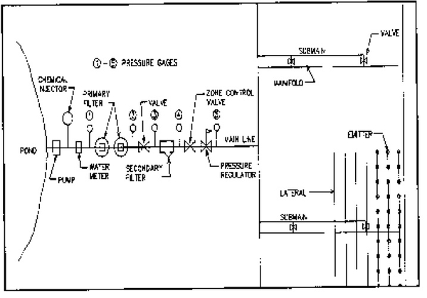
Figure 1 shows most of the components of a low volume system. The type of pump selected is normally governed by the water source. Straight centrifugal or self-priming centrifugal pumps are generally used on surface water sources. However, submersible or turbine pumps, which are normally used in wells, can be used on surface water supplies.
Power sources include electric, internal combustion engine (gasoline, liquid petroleum and diesel) and tractor PTO. Electric power is required for submersible pumps. The other types of pumps can be operated by any of the power sources. If the system is to be automated, electric power is preferred. High efficiency pumps should be selected whenever possible.
Filters and water distribution devices are discussed elsewhere in this paper. The pipe distribution system includes main line, sub-mains, manifolds pipe and lateral lines. The type of water distribution device (line source, point source and micro- spray, micro-spinner, and spray stake) determine some of the system hardware. The line source system includes the lateral line as an integral part of the emission device. The tube is manufactured of polyethylene (PE) plastic with a wall thickness of 4 to 25 mil. Generally, at least 8 mil wall thickness is recommended. If the tube is to be used for more than one season, a thicker wall is recommended. Most of the line source systems use a 0.5 inch diameter lateral line.
The lateral line for point source systems is normally high carbon, low density PE pipe. Wall thickness is normally 30 to 50 mil. Tube inside diameter will vary from 0.375 to 1 inch. The micro-sprinklers normally use a PE or polyvinyl chloride (PVC) plastic lateral line. A PE micro-tube conveys water from the lateral line to the micro-sprinkler.
Sub mains or manifold can be layflat hose, PE pipe or PVC pipe. Main line is normally PVC pipe, but layflat hose, PE pipe or metal pipe can be used.
Controls and monitoring equipment can simply be gate valves, check valves and pressure gages. For larger, more complicated systems, many are equipped with automatic controllers, electric or hydraulic valves, water meters, soil moisture monitoring equipment, and back flow prevention. Automatic controls and valves allow greater flexibility in operation of the system. A water meter allows the user to determine how much water is being used. Daily monitoring of the water meter will indicate when emitters or orifices are becoming clogged or when there is a significant leak in the system. Soil moisture equipment gives information on the adequacy of irrigation. Back flow prevention equipment protects water supplies from chemicals or fertilizers that might be back- siphoned into the water supply.
Fertilizer injectors allow the grower to add fertilizer on a regular basis. This should lead to yield increases and prevent fertilizer from leaving the site, either as deep seepage or as surface runoff. If chemicals are needed to adjust water quality, a chemical feed pump is needed. Also limited chemigation (mainly herbicides and nematocides) can be accomplished through the low volume system.
Water Distribution Devices
In the several decades since low volume irrigation was first introduced, there has been considerable improvement in the water distribution devices and a significant reduction in the number of potential suppliers. Some companies produce a fairly complete line of devices, while others offer only selected types. Water distribution devices can basically be classified as one of three types: 1) line source; 2) point source; and 3) low volume micro-sprays, micro- spinners, and spray stakes. At least one manufacturer has a product that combines some of the features of line source and point source.
Line-Source Systems
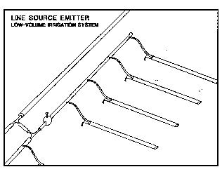
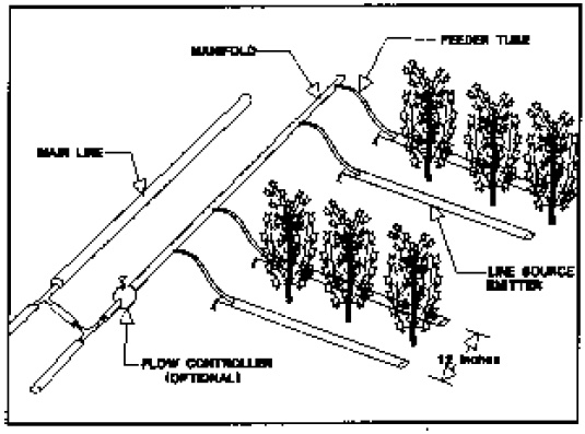
Most of the true line-source systems are used for row crops. Orifice spacing can vary from 4 to 60 inches, but most are 4-, 8-, or 12- inch. Generally, these systems are designed to operate at line pressures of 4 to 10 psi. Normally a non- pressure- compensating emitter or orifice is used. This limits their use to essentially level topography. Maximum row length is 200 to 600 feet depending on orifice spacing and design pressure. The trend with these systems is away from laminar flow and to turbulent flow which does a better job of preventing orifice clogging. Line-source systems are supplied by several manufacturers and product configuration and design varies, both in the type of orifice and the tube used. Products supplied by various manufacturers do perform satisfactorily. Some may be more acceptable than others. Line sources systems will generally apply the daily water needs to a crop in two hours or less. This allows a field or fields to be divided into several zones and still allow the entire area to be irrigated in one day. Figure 2 is a schematic of a line source system for vegetable crops.
Point-Source Systems
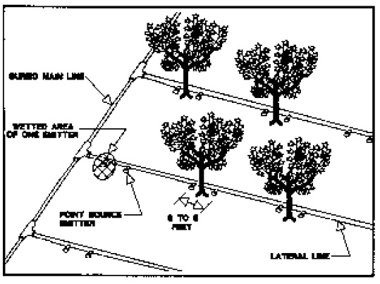
Point-source systems consist of emitters that are manufactured into the lateral line, those installed in sections of lateral line, those that can be attached to the outside of the lateral line or those that are attached to the lateral line by a micro-tube. The latter may be several feet from the lateral line. Figure 3 is a schematic of a point source system for tree fruits. To apply water needs for tree fruits with point source emitters may require 6 to 12 hours of operation per day. It may be possible to divide an orchard into two or three zones and sequence through the zones each day.
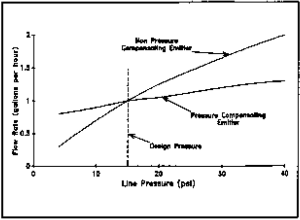
Both turbulent and laminar flow emitters are available. Also pressure compensating emitters and non-pressure compensating emitters are supplied. Most non-pressure compensating emitters are designed to operate at approximately 15 psi. The pressure compensating emitters will operate at 10 to 60 psi with approximately the same discharge rate. Normal discharge rates are 0.5, 1.0 or 2.0 gallons per hour (gph) for both pressure compensating and non-pressure compensating emitters. A few manufacturers provide emitters with flow rates lower than 0.5 ggh. Figure 4 shows the discharge (emitter flow rate) versus pressure from a nominal 1 gph emitter. Note that discharge rate is more constant for the pressure compensating emitter than for the non-pressure compensating emitter. Because of the more complex design, pressure compensating emitters have a higher initial cost.
There are also multi-outlet emitters, where up to six micro-tubes can be attached to irrigate areas around the emitter. Most point-source systems are designed to irrigate tree, shrub and vine crops. However, they can be used for row crops.
Micro-Spray Type Nozzle
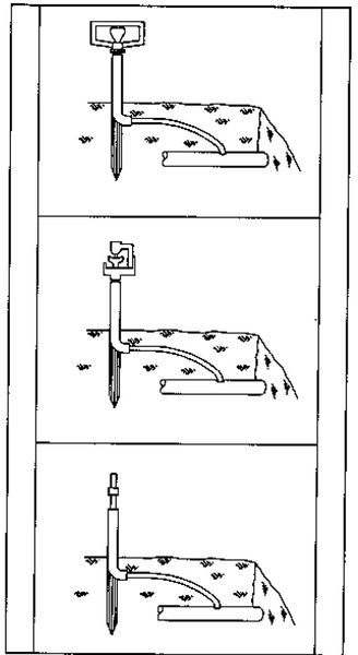
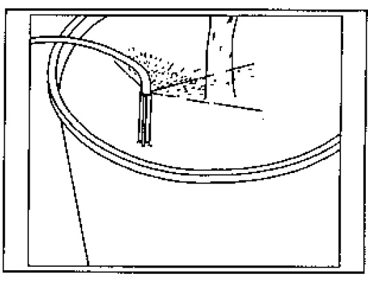
Micro-sprays, micro-spinners and spray stakes are small sprinklers, normally constructed of plastic. They are designed mainly for trees, shrubs, and nursery irrigation. They are designed to operate at 10 to 30 psi and have flow rates of 3 to 50 gallons per hour with coverage diameters of 2 to 50 feet. The micro-sprays and micro- spinners are normally mounted on a small plastic riser with a micro-tube to convey water from the lateral line to the application device. Figure 5 is a schematic of three different types of micro-sprays or micro- spinners. Most of these devices provide part circle coverage. A limited number are essentially full circle coverage except where the sprinkler arm support masks the spray nozzle. Spray stakes, which are normally used to irrigate container plants, are placed directly into the growing media. A micro-tube conveys water from the lateral line to the spray stake. Figure 6 shows a typical placement for a half-circle spray stake in a container.
Filtration
Due to the tiny water passages of the emitter, extremely clean water is required for all low volume systems. It is important to have a water analysis made prior to installing the filter system and to occasionally check the water to ascertain that quality has not changed. As a rule, the poorer the water quality, the greater the amount of filtration required. Both physical and chemical water quality needs to be examined.
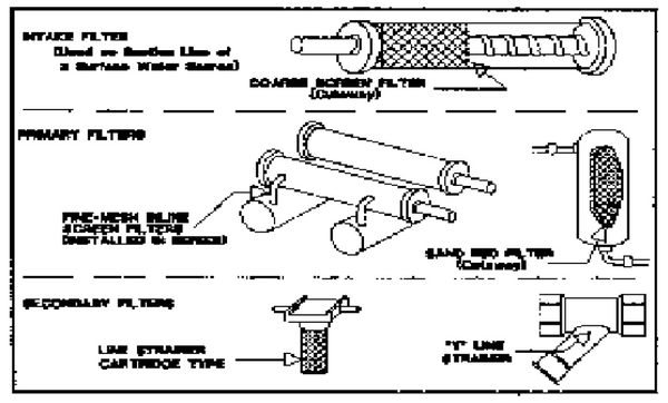
Filtration may include filters to remove materials found in the water and possibly chemical adjustment of the water. Filters are normally divided into primary filters and secondary filters. It is generally accepted that a sand media filter is the best primary filter and is a necessity for surface water supplies. Mechanical filters such as screen filters, sand separators and disc filters may also be used as primary filters for ground water supplies. Minerals in ground water may require the addition of chemicals such as acids, chlorine and softeners to ensure satisfactory operation of the filters.
Screen filters, "and separators, disc filters, in-line Y- strainers and cartridge filters are generally considered to be secondary filters. The primary filter is normally located next to the water source and the secondary filters are located nearer the point of delivery to the lateral lines. Figure 7 shows schematics of some of the different types of filters.
Chemicals, such as acids, chlorine, softeners, etc. are normally injected near the water source. Injection can be continuous feed or intermittent, depending on water quality. Individual chemicals or mixtures of chemicals may be injected.
Filters require cleaning (backwashing, flushing, or physical cleaning) to remove contaminants. If this is neglected, the filter becomes clogged and contaminants enter the drip system. Pressure drop across the filter is used as a guide on the frequency of cleaning. Generally, if the pressure drop exceeds 5 psi, the filter should be cleaned. Pressure gages should be placed on either side of the filter to indicate when cleaning is needed based on pressure drop across the filter. Sand media filters should be installed in tandem to allow filtered (clean) water to be used for backwashing. Water is forced back through the filter in the opposite direction to the filtering process to clean the filter and remove contaminants. Screen filters and disc filters may be flushed, backwashed or physically cleaned. Sand separators are normally flushed. (Contaminants are removed by opening a valve and letting water wash them out.)
Design of Low Volume Systems
Because low volume systems use water application devices that cover a small area and the system is designed to apply a small volume of water at one time, it is critical to insure that the system has adequate capacity to meet maximum evapotranspiration (ET) rates. Crop to be irrigated, size of crop, soil type or growing medium, crop canopy factor and ET rate all need to be considered. Once the daily water requirements have been determined, hardware can be selected. Since most systems are low pressure, the designer must minimize friction loss in sub-mains and laterals to assure essentially constant pressure to each emitter or orifice. Factors that affect friction loss are pipe size, type and length, number of outlets, and flow in the pipe. Friction loss can be determined from formula, tables, or slide rules. A competent designer will use all these tools to ensure a sound design.
Design rules for low volume systems are modified from those normally used for other types of irrigation systems. This is especially true for those systems using non-pressure compensating emitters or orifices. Since these systems operate at low pressure and it is desirable to have uniform discharge from each orifice, there can be little variation in pressure. For example, a line source system that requires 8 psi at the orifice should have a maximum pressure differential in the field of 1.6 psi (.20 x 8 of psi = 1.6 psi). The pressure loss should be divided between the sub-main and/or header in the field and the laterals.
The pressure loss should be proportional as follows: not over 45 percent in the sub-main and/or header and not over 55 percent in the lateral. For the system with orifice operating pressure of 8 psi, pressure drop in the sub-main and/or header should not exceed 0.72 psi. Pressure drop in the lateral should not exceed 0.88 psi. In practice, what the designer tries to accomplish is to have approximately 8 psi pressure at the head of each lateral. At the end of the lateral, pressure should be no less than 7.12 psi. In the header or sub-main supplying a group of laterals, pressure should not be greater than 8.72 psi.
If the field has elevation differences, it may be necessary to install pressure regulators on the main, sub-main, or header pipes. If laterals have to be installed on a slope, the laterals should be run down slope rather than upslope. This allows elevation change to counteract pipe friction loss.
The most efficient design is to zone field(s) so that a portion of the field is irrigated at one time. Once that section or zone is irrigated, another zone is irrigated. This allows the use of smaller pumps, power units, and main line. For vegetable crops, the most efficient irrigation is to operate each zone for 10 to 20 minutes at one time and then switch to another zone. To meet daily water needs, each zone might operate four to six times per day.
It is possible to utilize the same procedure for point-source emitters and micro-sprinklers or spray stakes. Certainly the designer needs to consider ways to minimize system initial cost and yet have a design that will meet peak crop water needs.
Source of Flow Variation
There are several factors that can account for flow variation in low volume systems. Emitter or orifice clogging due to inadequate filtration is probably the major problem. Other causes are non-uniformity of the manufactured product, water temperature change and hydraulic variation. Studies have shown that uniformity of water discharge can be greatly reduced when one to five percent of the emitters are clogged. Manufacturing variation (coefficient or manufacturing variation) can account for considerable variation in uniformity. (Testing of 50 lot samples of emitters from several manufacturers showed that emitters supplied by some manufacturers have considerably more flow variation than those supplied by other manufacturers.) A low value of coefficient of manufacturing variation is desired.
As water temperature increases, viscosity decreases and water discharge can increase. With uniform orifices or emitters and no friction loss in the lateral line, this can cause those emitters most distant from the header pipe to have a higher flow rate than the emitters closest to the header pipe. Water temperature can increase due to the flow of the water through the pipe. Sizes of main line pipe, header pipe and lateral line need to be considered in system design to insure that pressure loss due to friction does not adversely affect orifice discharge. This is more important for non-pressure compensating orifices than for pressure compensating emitters. It is equally important to consider the elevation changes on water pressure. For each 2.31 feet of change, there is a 1 psi differential.
Energy Efficiency
Low volume irrigation systems have the potential to be the most efficient systems available. However, system design, use, and maintenance are key in determining the actual system efficiency. In North Carolina, low volume irrigation is still in its infancy. A number of systems are being used where components are not well matched. Users are installing demonstration or trial systems to learn about low volume systems before they make a commitment to invest heavily in equipment. Often pumps that are used were designed for another type of system or an inexpensive, low efficiency pump was purchased. Insufficient filtration may result in partially or totally clogged emitters.
In areas where there is considerable elevation difference, high pump pressure may be required to provide adequate pressure at the highest elevation. Pressure regulators are needed to reduce that pressure at lower elevations. It may not be possible to overcome this problem, but it should be considered in the design.
Inadequate backwashing or flushing of filters can increase pressure and horsepower requirements. Ignoring leaks, clogged or partially clogged emitters, orifices or spray nozzles, dirty filters and/or pump and power unit performance will lead to inefficiency. Using main line, header pipe, or laterals that are too small will increase friction loss and lead to inefficiency and non-uniform water application. Selecting an inefficient pump, a pump with too high pressure, or an improperly matched pump and power unit can increase pumping costs. At times, using pressure compensating emitters rather than non-pressure compensating emitters with a couple of pressure reducing valves can reduce efficiency.
Conclusion
A low volume irrigation system is typically a low to medium pressure system that is designed to apply small volumes of water on a frequent basis. The entire system needs to be designed as a unit. Once it is installed, it should be used in the manner it was designed and should be properly maintained. Daily maintenance will be required. More management will be needed than for most other types of irrigation. Some of the newer systems in use in North Carolina have high pumping efficiencies and high overall water application efficiencies. Growers that are using these systems are benefiting financially with higher yields, more net profit, and doing a much better job of water management.
Publication date: June 1, 1996
Reviewed/Revised: July 26, 2024
N.C. Cooperative Extension prohibits discrimination and harassment regardless of age, color, disability, family and marital status, gender identity, national origin, political beliefs, race, religion, sex (including pregnancy), sexual orientation and veteran status.

